KemroX Custom Robot
With the drag&bot KemroX robot driver it is possible to display and control a self-defined kinematic which was created in KeStudio. The robot is controlled from drag&bot with the KemroX RcApi interface, while the displayed robot kinematic, meshes and settings can be configured by the user.
Prerequisites
This tutorial assumes
- that you are familiar on how to use the drag&bot overlay system.
- that you are familiar using git and that git installed on the target system.
- that a valid URDF file with mesh files for each robot link does exist. Otherwise, it is not possible to show a robot model in drag&bot.
Setup
- Clone the dnb_kemrox_custom_robot ROS package into the drag&bot overlay.
- Add/Modify the files in the package for the robot to be integrated:
URDF File
The URDF (Unified Robot Description Format) file describes the kinematic of the robot. Here the chain of alternating links and joints is described. Each link is represented by one transformation (tf) frame, where a mesh is attached to. Later, when the joint values are received from the controller, these are applied to each joint and the displayed robot is placed in the corresponding position. In drag&bot the URDF file is almost exclusively used for displaying purposes. The following graph shows the chain of links and joints for a six-axis robot as it is used in drag&bot:
By convention robot URDFs always start with the base_link frame/link and end with ee_link. The joints are named joint_1 to joint_6 for a six axes robot.
Adjust your URDF file to meet the naming conventions of the joint and link names and save it as custom_robot.urdf in the urdf/robot directory of the ROS package. You can use the existing file as a template when creating the URDF from scratch.
Mesh Files
The robots mesh files are placed in the meshes directory of the ROS package. Maybe you have to adjust the stated mesh paths in the URDF file respectively.
Module Config Files
The robots' module config file module_config/robot/kemrox_custom.yaml needs to be adjusted. Most of its parameters are for the drag&bot control panel and should already work. The joint limit parameters however might have to be adjusted. See the Control Panel interface how to configure the parameters for the control panel.
After all settings are configured, restart the robot system.
Setup for drag&bot Studio
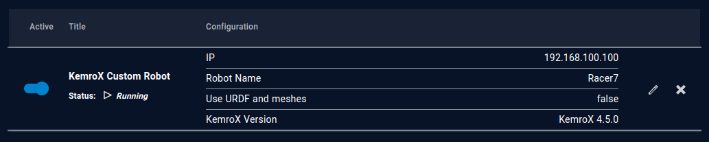
- Select KemroX Custom Robot from the dropdown menu in the drag&bot Component Manger.
- Configure the parameter IP for your setup. It has to match with the IP address noted from the KeStudio setup. By default, a KemroX robots IP address is
192.168.100.100. - Configure the parameter Robot Name. It has to match with the robot name noted from the KeStudio setup.
- Activate the option Use URDF and meshes, if these are configured in the ROS package described above. Deactivate the option otherwise to avoid loading of non-existent files.
- Configure the KemroX Version of the PLC.