ABB Controller Setup
Requirements
The software options 616-1 "PC Interface" and 623-1 "Multitasking" are required to be installed on the robot controller. Further the option "Engineering Tools / Auto acknowledge input" needs to be activated.
Downloads
The required controller files can be downloaded from here: Downloads
Configure WAN IP
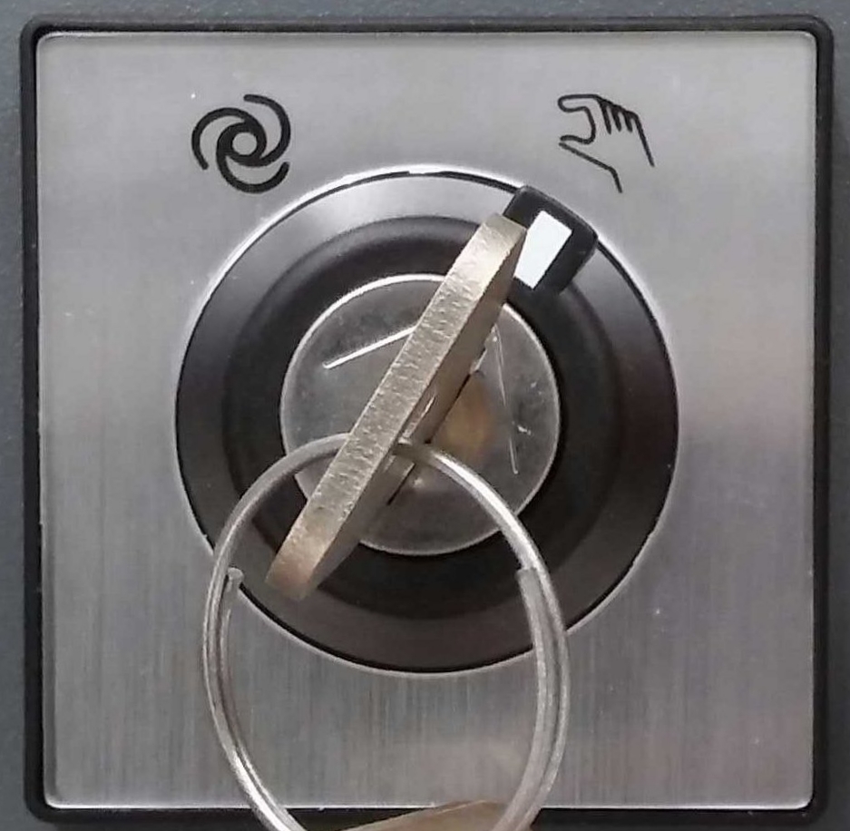
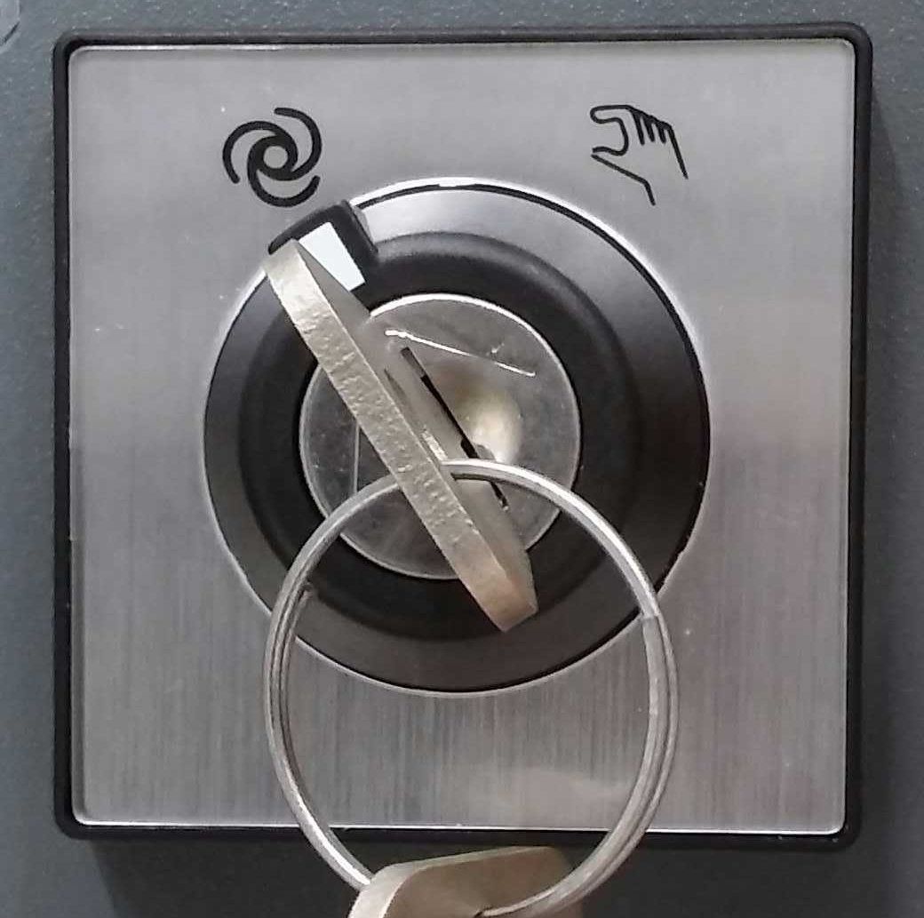
- Switch the controller to Manual Mode
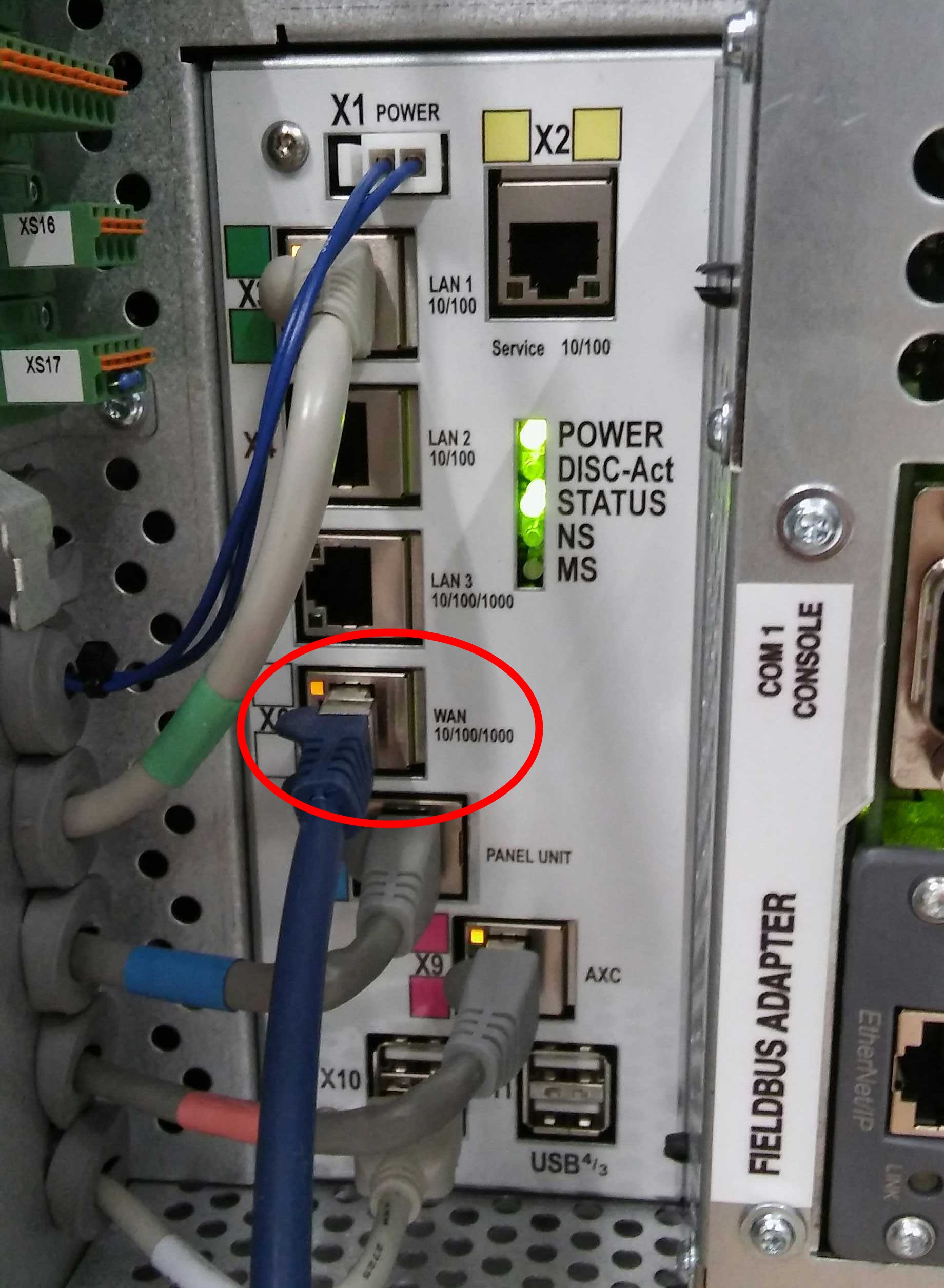
- Connect the IPC with the WAN Port of the controller
-
Configure the Controllers WAN IP with the control panel
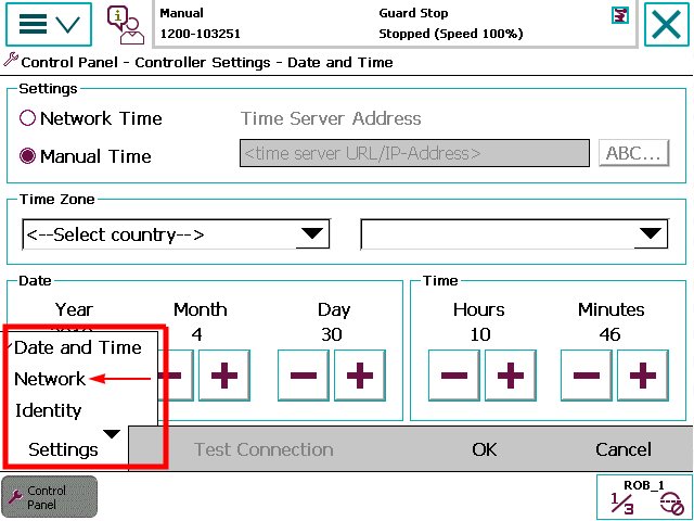
- Switch to Menu (3 horizontal lines at top left corner) -> Control Panel -> Controller Settings
- Change the Settings view on the bottom bar left to Network
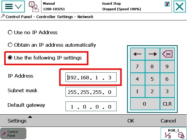
- Configure to use a static IP and set the IP for the controller (default for drag&bot: 192.168.1.3)
Calibrate Axes
- Switch the controller to Manual Mode
- Switch at the teach pendant to Menu -> Jogging
- Jog all axes to the mechanical zero indicators at the robot: To move a axis keep the release button pressed and move the joystick in the respective direction. Which direction corresponds to which axis is displayed in the bottom right corner. To switch from axes 1, 2 and 3 to the axes 4, 5 and 6 change the motion mode in the jogging view. Here you can also change to linear movement mode and reorientation mode. The motion mode can also be changed with the soft buttons
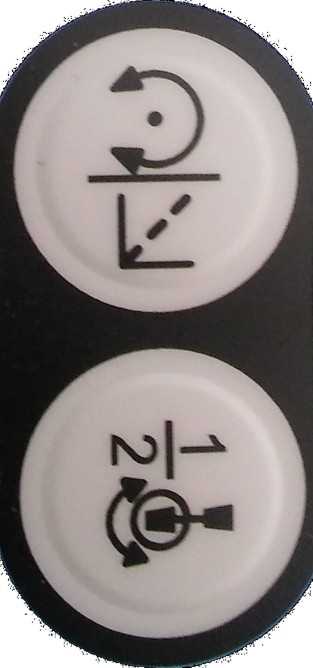 , where the first changes between linear movement and reorientation mode and the second between joint axes 1, 2 and 3 and the joint axes 4, 5 and 6.
 - Switch at the tech pendant to Menu -> Calibration
- Select Manual Method (Advanced) in the bottom bar
- Select the Tab "Rev. Counters", Press "Update revolution Counters ...", Confirm to proceed, select all joints and press update twice
Connect Controller with RobotStudio
This works both for the active 30-days-free-version, the expired 30-days-free-version and the premium version.
- Start RobotStudio
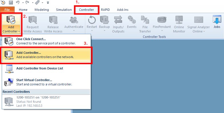
- Switch to the Controller Tab and add a new controller from the network.
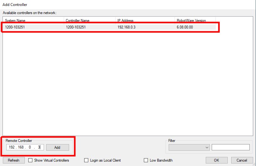
- If the controller was automatically detected select it and press "OK". Otherwise enter the controllers WAN IP in the bottom left section and search for it.
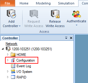
- When the controller is connected to RobotStudio, in the controller tab the system tree appears on the left side.
Configure Controller for drag&bot with RobotStudio
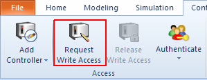
- Request Write Access at the Controller Tab. In manual mode you will be asked to grant access at the teach pendant. In automatic mode the access is granted automatically.
Prepare the configuration files
- Preparation of the configuration files is done based on the existing ABB configuration files on the controller. Here the configuration for the drag&bot system is simply added.
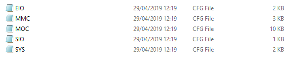
- At first make a copy of the existing files on the controller to the connected computer. For this right Click on Configuration in the system tree and select Save Parameters ....
- Deselect all configuration groups except Controller and I/O System, press Save ... and select an empty directory. Two files SYS.cfg and EIO.cfg for the two configuration groups will be downloaded to the chosen directory.
- Download and unzip the correct drag&bot IRC5 controller config files from here.
- Use the content of the two matching DNB files which you just unzipped to the corresponding configuration files from the controller, depending your controller provides a DSQC 652 Board to handle digital I/Os. The IRC5 compact controller has a DSQC 652 Board integrated by default. Just one DSQC 652 Board is supported.
- You will notice, that there are several categories in each file, e.g. SYSSIG_OUT, SYSSIG_IN, etc. For each category add the entries from the DNB config file to the respective category in the controllers file. If a category does not yet exist, add it in the same way as the other categories.
Load the configuration files
- Right Click on Configuration in the system tree and select Load Parameters ....
- Switch to the directory with the adjusted ABB configuration files.
- Select the configuration files (multi-select works) and load them. Confirm that duplicated files will be replaced.
-
If you intend to use the ABB robot with the KEBA KeTop, additional configuration is necessary. Using the KeTop with the IRC5 controller is only possible with a DSQC 652 Board (or equivalent).
- Open the file EIO-safe_teaching.cfg in a text editor.
- Search the entry triggerLimitSpeed in the group EIO_SIGNAL.
- A digital input of the ABB controller is used to limit the speed in KeTop teach mode to 250mm/s.
- This input is triggered by a digital output of the KEBA CP520 to activate the limitation during the teach mode of the KeTop.
- Configure the number of the ABBs digital input at DeviceMap, where the CP520 limit speed signal is connected to.
- By default, the value is 0, indicating the digital input 1.
- The used digital input can not be used for any other functionality.
- After configuring, save the file and load it like the other configuration files before.
-
If you want to be able to pause the robots movement execution via digital I/O, additional configuration is necessary. This is only possible with a DSQC 652 Board (or equivalent).
- Open the file EIO-pause_resume.cfg in a text editor.
- Search the entry triggerPause in the group EIO_SIGNAL.
- A digital input or output of the ABB controller is used to trigger the movement pause.
- Configure the number of the ABBs digital input or output at DeviceMap, where the pausing should be triggered.
- A digital output should only be used, if the robot controller itself should be able to trigger the pause.
- By default, the value is 0, indicating the digital I/O 1.
- Change the field SignalType from DI to DO, if you are using a digital output.
- The used digital I/O can not be used for any other functionality.
- A rising flank of this signal will pause the robots motion immediately. A falling flank of this signal will resume the robots motion. While paused the robots motor control will remain active.
- Please note that this is not a sufficient setup for a Stop Category 2 of IEC 60204-1, as the standstill of the robot is not monitored from the robots safety system! Additional configuration in the ABB Safety Setup is required for this.
- After configuring, save the file and load it like the other configuration files before.
-
After loading confirm, that changes will not take effect until the controller is restarted.
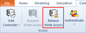
- Release Write Access at the Controller Tab. In manual mode you can alternatively revoke the access from the teach pendant.
- Restart the controller with the tech pendant via Menu -> Restart. Press Restart on the bottom bar.
- After restart the teach pendant might show an error or warning, which is OK, but must be acknowledged.
Load the program files
- Download and unzip the correct drag&bot IRC5 controller RAPID files from here.
- At the top bar click the File Transfer button (1).
- On the right half of the appearing window create a new directory "DNB" in "/
/ /HOME/", e.g. "/hd0a/1200-103251/HOME/DNB" (2). - Copy the unzipped files to the "DNB" directory by multi-select them on the left and press the => button (3) in the middle. Eventually confirm overwriting already existing files.
![]()
- Restart the controller with a RAPID-Restart with the tech pendant via Menu -> Restart. Press Advanced ... on the bottom bar and select Reset RAPID. Confirm with "Next" and press "Reset RAPID" in the bottom bar.
-
After restart the teach pendant might show an error or warning, which is ok, but must be acknowledged.
-
Switch the controller to Automatic Mode and confirm the warning on the teach pendant.
Digital I/Os
- Digital I/Os can only be used with a configured DSQC 652 Board. Just one DSQC 652 Board is supported. The IRC5 compact controller has a DSQC 652 Board integrated by default.
- To use the Digital I/Os the controller has to be configured with the "DSQC 652 Board" configuration. Further the respective option in the drag&bot component has to be selected.
- For wiring and pin layout of the IRC5 compact, consider the following image and table:
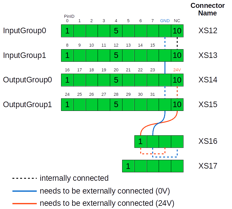
| Connector | Connector Ports | Type | drag&bot Pins |
|---|---|---|---|
| XS12 | 1 to 8 | Digital Input | DI[1] to DI[8] |
| XS12 | 9 | GND | - |
| XS12 | 10 | not connected | - |
| XS13 | 1 to 8 | Digital Input | DI[9] to DI[16] |
| XS13 | 9 | GND | - |
| XS13 | 10 | not connected | - |
| XS14 | 1 to 8 | Digital Output | DO[1] to DI[8] |
| XS14 | 9 | GND | - |
| XS14 | 10 | 24V | - |
| XS15 | 1 to 8 | Digital Output | DO[9] to DO[16] |
| XS15 | 9 | GND | - |
| XS15 | 10 | 24V | - |
| XS16 | 1 and 3 | 24V | - |
| XS16 | 2 and 4 | GND | - |
To interact with the Digital I/Os using this numbering in your programs use the function blocks
- Digital I/O Device - Get
- Digital I/O Device - Set
- Digital I/O Device - Wait For
as described in the Function Block Library overview.
Additional Hints
Encoder Batteries
Always ensure that the robot encoder batteries do not completely discharge. Otherwise a re-mastering of the robot might be necessary. For more information see the respective robot manual and the Operating manual: Trouble shooting, IRC5.