Basler cameras
Requirements
Make sure to add also the Vision Module component to your component setup. This is required to show the camera image in the drag&bot Studio and perform the calibration.
Requirements
Any pylon 5 or higher Basler compatible camera is required. Although all models are theoretically supported, tests where made with the models acA1440-73gm, daA1600-60uc and acA2440-35um. In case of doubt, please contact support@dragandbot.com us to know if an specific camera model is supported.
For ethernet cameras it may be required an ethernet power injector. Using an ethernet switch would be recommended to allow adding more ethernet hardware components to the IPC in the future.
1. Installation
Basler provides two types of ROS compatible cameras:
- USB Cameras
- Ethernet Cameras
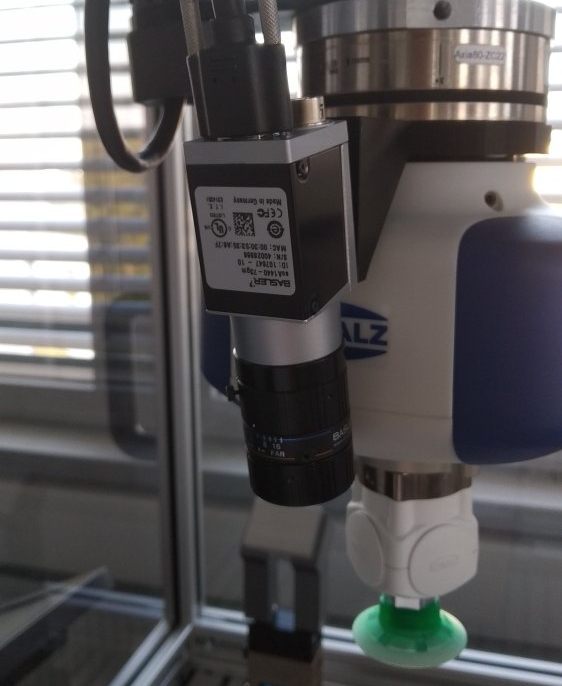
Cameras can be physically attached at the robot flange or statically attached to the cell. In case of the camera attached to the flange, we recommend that they are pointing in the same direction as the Z component of the tool transformation.
1.1. USB cameras installation
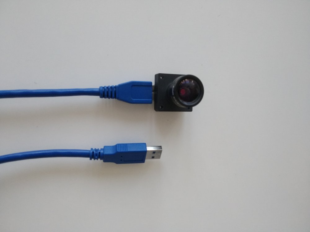
The USB cameras work plug-and-play. Just connect the camera to any USB port. We suggest using an available USB 3.0 port in order to achieve maximal transfer speed and therefore better framerate.
1.2. Ethernet cameras installation
- Connect the ethernet cable from the camera to the power injector. Please be sure that the power injector is powered.
- Connect a second ethernet cable from the power injector directly to a ethernet port at the IPC or to an ethernet switch.
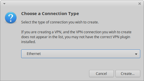
- Configure the IP address of your network adapter and your camera. Generally, there are two approaches to configuring a network adapter: "Fixed IP Address" or "DHCP / Auto IP (LLA) sometimes also referred to as APIPA (Automatic Private IP Addressing)".
We strongly recommend to change the camera to a fix IP in the range of other ethernet components (e.g. robot ip) as it is explained in Change IP from Linux section.
Camera IP can be configured from Windows PC or from a Linux PC (e.g. drag&bot IPC). For advance configuration details please refer to the Basler website.
1.2.1. Fast configuration from Linux
You have two options, connect the camera directly to the IPC or through a network switch.
Option 1: direct
- Connect the Basler ethernet cable directly from the power injector to a free ethernet port.
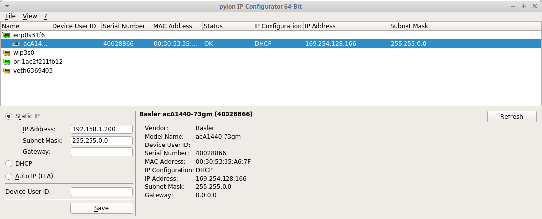
- Create a new configuration with a fix IP inside the range starting from 169.254.0.0 to 169.254.255.255 and with a netmask of 255.255.0.0.
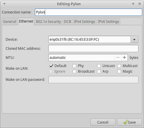
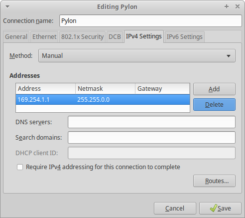
- Restart drag&bot Runtime after network configuration.
- Open the Camera Tab in the Operators panel. The camera image should now be shown.
Option 2: through switch
If you have connected the IPC to a switch you can create a second IP using the same ethernet port.
- Follow the steps 1-2 in the Option 1.
- Afterwards you need to click to add a second line of Address and Netmask.
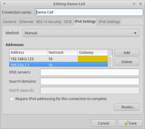
- Please be sure for both IPs the netmask is 255.255.0.0 (16) and they don't collide in range.
- Restart drag&bot Runtime after network configuration.
- Open the Camera Tab in the Operators panel. The camera image should now be shown.
1.2.2. Change IP from Linux (Advance configuration)
You need to install the Pylon Suite in order to change the IP address. You can download the debian package from:
After downloading the software follow these steps:
- Double click to start installation.
- Please click
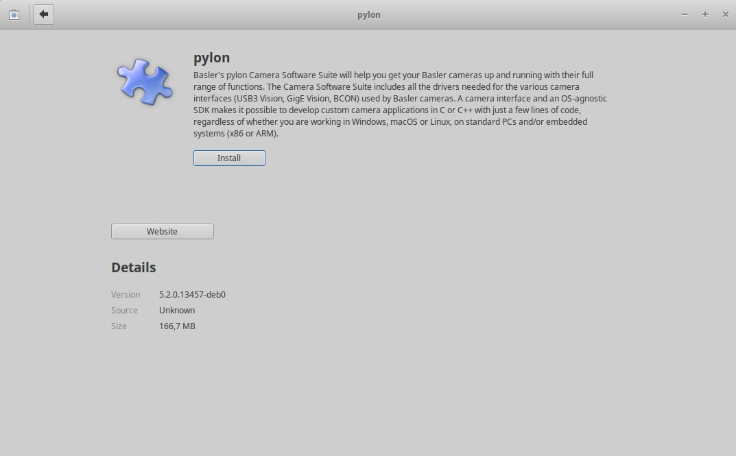
- Write the computer password when requested (typically: dragandbot) .
After the installation two applications will be available:
- pylon Viewer
- pylon IP Configurator
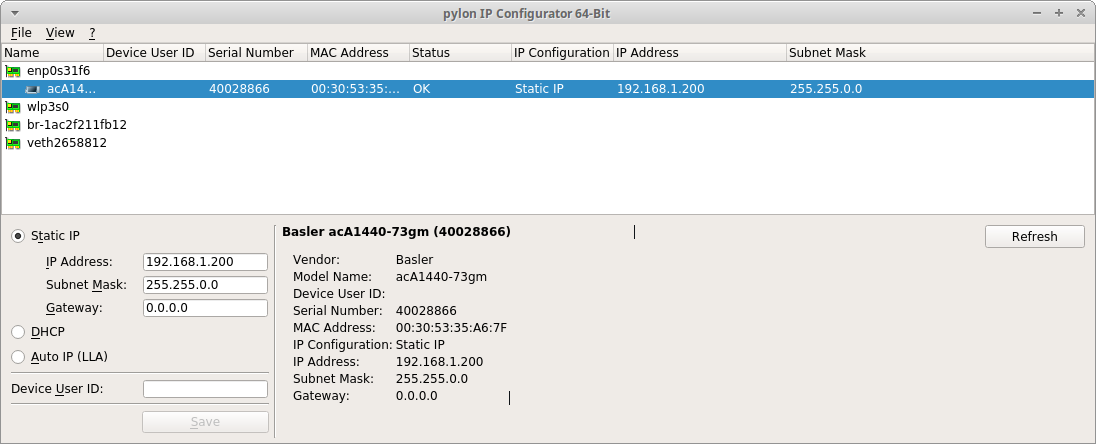
After following 1.2.1. Fast configuration from Linux section, you will be able to change the IP address of the camera through pylon IP Configurator Basler application which will be installed in your Linux (Ubuntu) system. Yo can change the ip and the mask to the same range you are using with other devices. This will enable using the camera through a network switch.
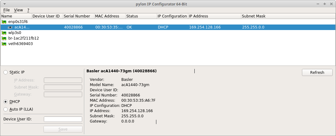
Note
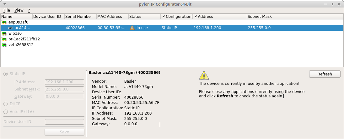
After changing the IP to a new range the program will be unresponsive. This means the IP was changed and therefore the current connection breaks. Then you will need to change your computer IP range to connect to the camera again.
The Basler component inside drag&bot will discover any camera IP in range automatically and therefore Running will be displayed after network restart / drag&bot Runtime restart.

1.2.3. Advance configuration from Windows
To configure your network adapter, please follow the procedure described in chapter "Installing a GigE Camera" of the current Install and Setup Guide for Cameras Used with pylon for Windows.
To change your camera’s IP configuration, you can use the pylon IP Configurator. This tool was automatically installed when you installed the pylon Viewer and selected the GigE interface. Detailed information about using the IP Configuration Tool can also be found in the "Installation Guide" mentioned above.
2. Basler component configuration
Once the camera is detected the component will display Running in the drag&bot Component-Manager. There are two configuration parameters available:
- Startup user set: The profile of camera configuration which will be loaded at the component start.
- MTU parameter. Advance configuration parameter. Please don't change it unless you are an expert.
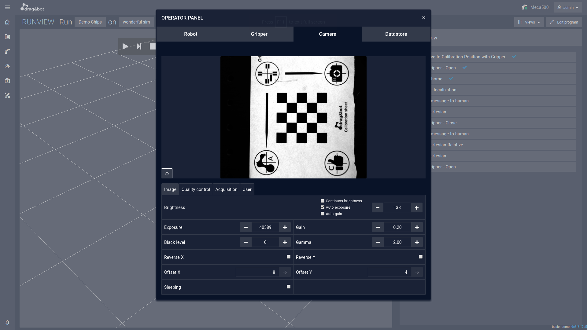
3. Camera control panel
Once the camera is up and running a new wizard will be available in the Operator Panel together with Robot, Gripper, etc. The camera configuration can be modified from this panel. The current picture will be also live displayed. Please read the tool tips directly available in the panel for further usage information.
 below are a short description of the basler control panel parameters, for more details refer to your Basler camera manual.
Important
The deactivated features in the camera Control Panel means that your camera is not supporting them.
Image Tab
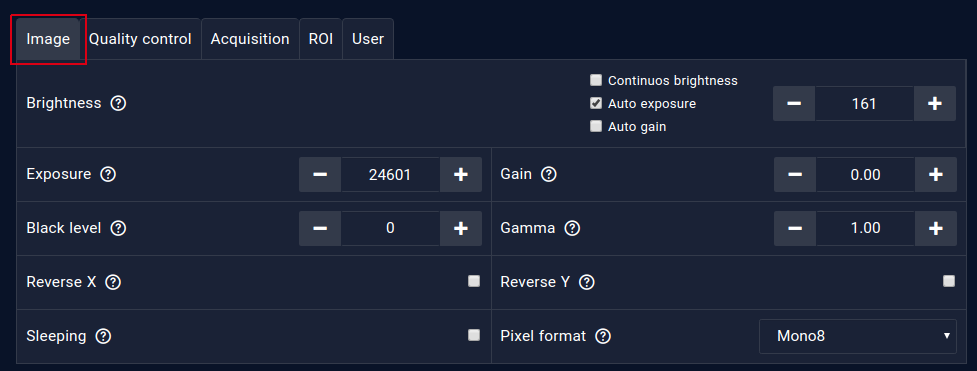
| Parameters | Description |
|---|---|
| Brightness |
|
| Continuous brightness |
|
| Auto exposure |
|
| Auto gain |
|
| Exposure |
|
| Gain |
|
| Black Level |
|
| Gamma |
|
| Reverse X |
|
| Reverse Y |
|
| Sleeping | Stop publishing the Image as far as its activate. |
| Pixel format |
|
Qualit control Tab
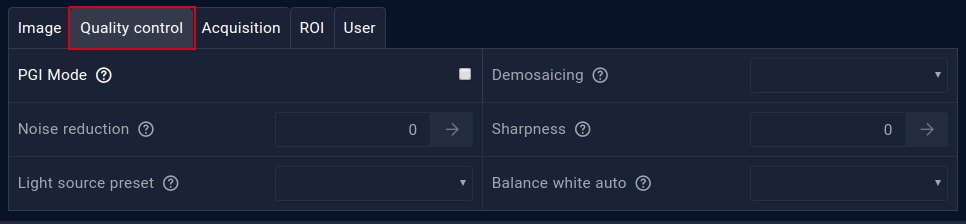
| Parameters | Description |
|---|---|
| PGI Mode |
|
| Demosaicing |
|
| Noise reduction |
|
| Sharpness |
|
| Light source preset | Allows you to correct color shifts caused by certain light sources. |
| Balance white auto | Automatically corrects color shifts in images acquired. |
Acquisition Tab
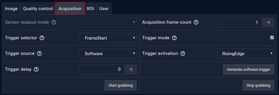
| Parameters | Description |
|---|---|
| Sensor readout mode |
|
| Acquisition frame count | The number of images per camera trigger (Refer to Trigger selector : AcquisitionStart) |
| Trigger selector |
|
| Trigger mode |
|
| Trigger source |
|
| Trigger Activation |
|
| Trigger delay |
|
| Generate software trigger | Allows you to trigger the camera by executing a software command. |
| Start grabbing | Start the image grapping. |
| Stop grabbing | Stop the image grabbing. |
Important
Changing of some camera parameters will required to manually stop the image grabbing Stop grabbing , change the parameter(s), then start image grabbing Start grabbing
ROI Tab
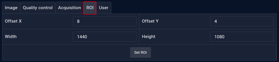
| Parameters | Description |
|---|---|
| ROI |
|
| Offset X | Specify the X position of the image ROI |
| Offset Y | Specify the Y position of the image ROI |
| Width | Specify the width size of the image ROI |
| Height | Specify the height size of the image ROI |
Important
The ROI parameters (Offset X, Offset Y, Width, and Height) are setted all as a one parameter group.
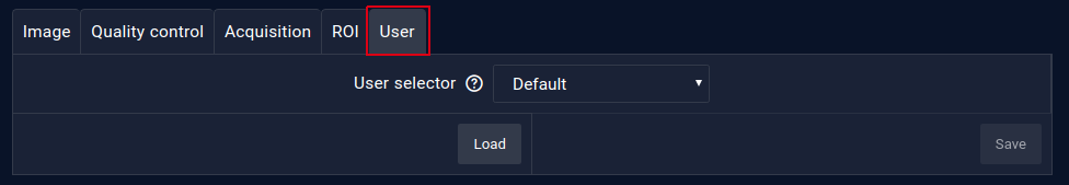
User Tab
| Parameters | Description |
|---|---|
| User selector |
|
| Load | Allow you to load camera parameters that are stored in the selected user selector |
| Save | Allow you to save the current camera parameters to a user set, work only in case of User Set 1, User Set2, and User Set 3 |