KeTop
This section describes the requirements to use the KeTop with the drag&bot OS. After adding the KeTop device to the KeStudio project, you need to link its keys to variables that make them available to the drag&bot OS. For doing this, there are two methods to communicate between the KeTop and the drag&bot system:
- Option 1 : Variable client/server, supported for KemroX V4.5.0 and higher versions (default option).
- Option 2 : Modbus TCP/IP, should be used for the older KemroX versions (require an addition KemroX Modbus license).
Option 1: Variable client/server interface
Important
This interface is compatible with the KemroX V4.5.0 and higher.
Setup KeStudio Project
GVL Configuration
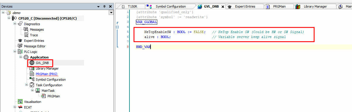
You need to set up the global variables for the KeTop enable switch signal and the variable signal server. For doing this, open the GVL_DNB file and add code below. The KeTopEnableSW variable should be linked to the KeTop enabling switch by any means of communication (a hard wired digital I/O or a software signal).
    KeTopEnableSW : BOOL := FALSE;   // KeTop Enable SW (Could be HW or SW Signal)

    alive : BOOL;                    // Variable server keep alive signal
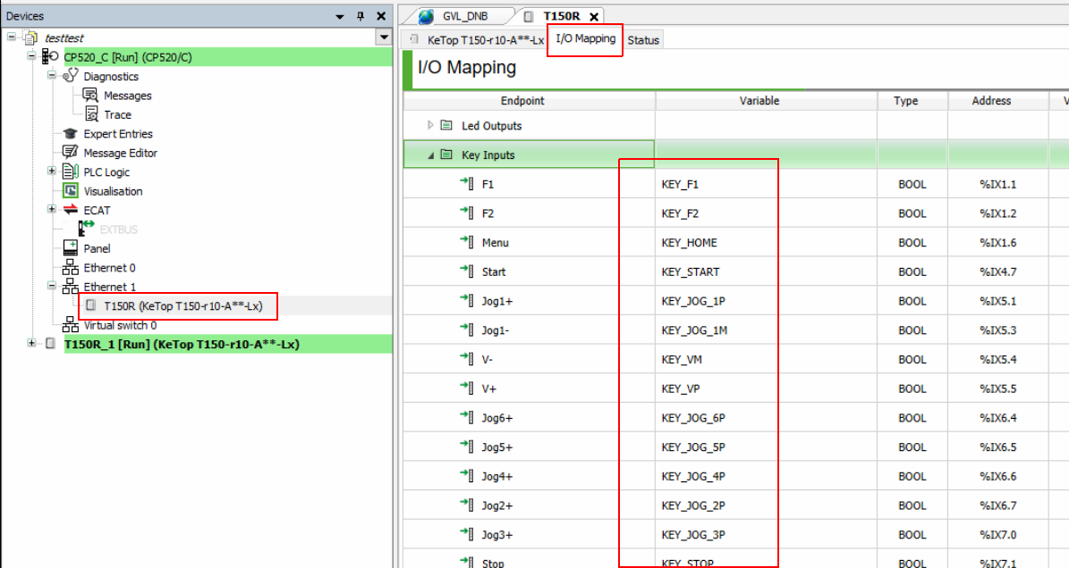
KeTop IOs Mapping
In the KeTop device, open the I/O Mapping and link the KeTop variables as shown in the table below.
| # | Key Inputs | Variable | # | Key Inputs | Variable |
|---|---|---|---|---|---|
| 1 | F1 | KEY_F1 | 14 | Stop | KEY_STOP |
| 2 | F2 | KEY_F2 | 15 | Jog6- | KEY_JOG_6M |
| 3 | Menu | KEY_HOME | 16 | Jog5- | KEY_JOG_5M |
| 4 | Start | KEY_START | 17 | Jog4- | KEY_JOG_4M |
| 5 | Jog1+ | KEY_JOG_1P | 18 | Jog2- | KEY_JOG_2M |
| 6 | Jog1- | KEY_JOG_1M | 19 | 2nd | KEY_2nd |
| 7 | V- | KEY_VM | 20 | Jog3- | KEY_JOG_3M |
| 8 | V+ | KEY_VP | 21 | Step | KEY_STEP |
| 9 | Jog6+ | KEY_JOG_6P | 22 | Jog | KEY_JOG_0 |
| 10 | Jog5+ | KEY_JOG_5P | 23 | PWR(MOT) | KEY_PWR |
| 11 | Jog4+ | KEY_JOG_4P | 24 | Key switch position 2 | KEY_SW_RIGHT |
| 12 | Jog2+ | KEY_JOG_2P | 25 | Key switch position 1 | KEY_SW_LEFT |
| 13 | Jog3+ | KEY_JOG_3P |
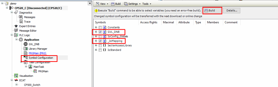
Symbol Configuration
Open the Symbol Configuration menu and select the GVL_DNB and _IoMapping then click on Build.
Project Building:
Now build the KemroX project by clicking on Build from the Build menu then download it to the KEBA controller using the Online menu then Selective Download to Device.
drag&bot Usage
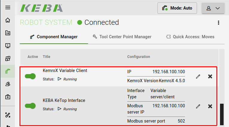
At the drag&bot OS, go to the component manger in the Robot System tab and add the KemroX Variable Client. The IP address should be the KEBA controller IP address and the KemroX Version should be "KemroX 4.5.0". Also, add the KEBA KeTop Interface component with the option "interface Type" set as "Variable server/client" (ignore the Modbus IP & port addresses). Now you are ready to start using the KeTop with the drag&bot OS.
Option 2: Modbus TCP/IP interface
Setup KeStudio Project
Setting up the Modbus Server:
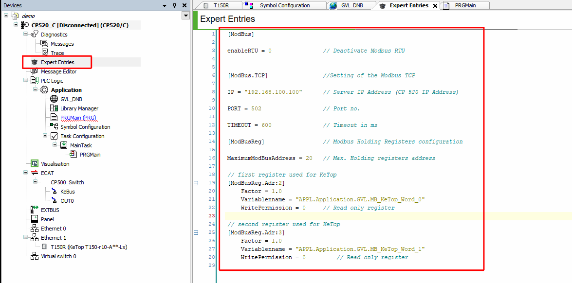
Open the Expert Entries and add the code below.
[ModBus]

enableRTU = 0               // Deactivate Modbus RTU


[ModBus.TCP]                //Setting of the Modbus TCP

IP = "192.168.100.100"      // Server IP Address (CP 520 IP Address)

PORT = 502                  // Port no.

TIMEOUT = 600               // Timeout in ms

[ModBusReg]                 // Modbus Holding Registers configuration

MaximumModBusAddress = 20   // Max. Holding registers address

// first register used for KeTop
[ModBusReg.Adr:2]
    Factor = 1.0
    Variablenname = "APPL.Application.GVL.MB_KeTop_Word_0"
    WritePermission = 0     // Read only register

// second register used for KeTop
[ModBusReg.Adr:3]
    Factor = 1.0
    Variablenname = "APPL.Application.GVL.MB_KeTop_Word_1"
    WritePermission = 0         // Read only register
GVL Configuration
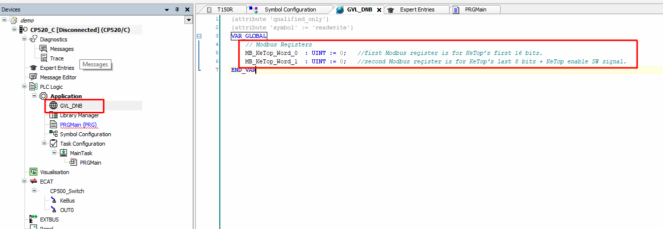
You need to set up the global variables for the MODBUS server. For doing this, open the GVL_DNB file and add code below.
    // Modbus Registers
    MB_KeTop_Word_0  : UINT := 0;   //first Modbus register is for KeTop’s first 16 bits.
    MB_KeTop_Word_1  : UINT := 0;   //second Modbus register is for KeTop's last 8 bits + KeTop enable SW signal.
KeTop IOs Mapping
In the KeTop device, open the I/O Mapping and link the KeTop variables as shown in the table below.
| # | Key Inputs | Variable | # | Key Inputs | Variable |
|---|---|---|---|---|---|
| 1 | F1 | KEY_F1 | 14 | Stop | KEY_STOP |
| 2 | F2 | KEY_F2 | 15 | Jog6- | KEY_JOG_6M |
| 3 | Menu | KEY_HOME | 16 | Jog5- | KEY_JOG_5M |
| 4 | Start | KEY_START | 17 | Jog4- | KEY_JOG_4M |
| 5 | Jog1+ | KEY_JOG_1P | 18 | Jog2- | KEY_JOG_2M |
| 6 | Jog1- | KEY_JOG_1M | 19 | 2nd | KEY_2nd |
| 7 | V- | KEY_VM | 20 | Jog3- | KEY_JOG_3M |
| 8 | V+ | KEY_VP | 21 | Step | KEY_STEP |
| 9 | Jog6+ | KEY_JOG_6P | 22 | Jog | KEY_JOG_0 |
| 10 | Jog5+ | KEY_JOG_5P | 23 | PWR(MOT) | KEY_PWR |
| 11 | Jog4+ | KEY_JOG_4P | 24 | Key switch position 2 | KEY_SW_RIGHT |
| 12 | Jog2+ | KEY_JOG_2P | 25 | Key switch position 1 | KEY_SW_LEFT |
| 13 | Jog3+ | KEY_JOG_3P |
Symbol Configuration
Open the Symbol Configuration menu and select the GVL_DNB and _IoMapping then click on Build.
Setup Modbus Task:
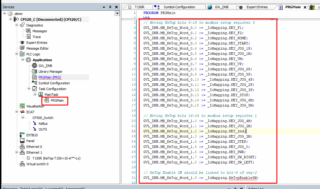
Open the PLC main task and add code below. The task should have cyclic time of 8 ms. This is used to link the Modbus registers (each register consist of 16 bits) to the individual Ketop keys.
// Moving KeTop bits 0-15 to modbus ketop register 0
GVL_DNB.MB_KeTop_Word_0.0 := _IoMapping.KEY_F1;
GVL_DNB.MB_KeTop_Word_0.1 := _IoMapping.KEY_F2;
GVL_DNB.MB_KeTop_Word_0.2 := _IoMapping.KEY_HOME;
GVL_DNB.MB_KeTop_Word_0.3 := _IoMapping.KEY_START;
GVL_DNB.MB_KeTop_Word_0.4 := _IoMapping.KEY_JOG_1P;
GVL_DNB.MB_KeTop_Word_0.5 := _IoMapping.KEY_JOG_1M;
GVL_DNB.MB_KeTop_Word_0.6 := _IoMapping.KEY_VM;
GVL_DNB.MB_KeTop_Word_0.7 := _IoMapping.KEY_VP;
GVL_DNB.MB_KeTop_Word_0.8 := _IoMapping.KEY_JOG_6P;
GVL_DNB.MB_KeTop_Word_0.9 := _IoMapping.KEY_JOG_5P;
GVL_DNB.MB_KeTop_Word_0.10 := _IoMapping.KEY_JOG_4P;
GVL_DNB.MB_KeTop_Word_0.11 := _IoMapping.KEY_JOG_2P;
GVL_DNB.MB_KeTop_Word_0.12 := _IoMapping.KEY_JOG_3P;
GVL_DNB.MB_KeTop_Word_0.13 := _IoMapping.KEY_STOP;
GVL_DNB.MB_KeTop_Word_0.14 := _IoMapping.KEY_JOG_6M;
GVL_DNB.MB_KeTop_Word_0.15 := _IoMapping.KEY_JOG_5M;

// Moving KeTop bits 16-24 to modbus ketop register 1
GVL_DNB.MB_KeTop_Word_1.0 := _IoMapping.KEY_JOG_4M;
GVL_DNB.MB_KeTop_Word_1.1 := _IoMapping.KEY_JOG_2M;
GVL_DNB.MB_KeTop_Word_1.2 := _IoMapping.KEY_2nd;
GVL_DNB.MB_KeTop_Word_1.3 := _IoMapping.KEY_JOG_3M;
GVL_DNB.MB_KeTop_Word_1.4 := _IoMapping.KEY_STEP;
GVL_DNB.MB_KeTop_Word_1.5 := _IoMapping.KEY_JOG_0;
GVL_DNB.MB_KeTop_Word_1.6 := _IoMapping.KEY_PWR;
GVL_DNB.MB_KeTop_Word_1.7 := _IoMapping.KEY_SW_RIGHT;
GVL_DNB.MB_KeTop_Word_1.8 := _IoMapping.KEY_SW_LEFT;

// KeTop Enable SW should be linked to bit-9 of reg-2
GVL_DNB.MB_KeTop_Word_1.9 := _IoMapping.KeTopEnableSW;      // _IoMapping.KeTopEnableSW should be mapped to the KeTop enabling SW.
Project Building:
Now build the KemroX project by clicking on the Build from the Build menu then download it to the KEBA controller using the Online menu then Selective Download to Device.
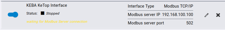
drag&bot Usage
In drag&bot, open the component manger in robot system tab, then add the component. The interface type should be Modbus TCP/IP. The Modbus server IP and port should be the KEBA controller IP address and port numbers from step Setting up the Modbus Server above.