Setup of Balluff Smart Camera with drag&bot
Network Configuration
By default the Balluff Smartcamera can be accessed in a dynamic network, where ip addresses are provided by DHCP. However drag&bot usually works in a network of static ip addresses.
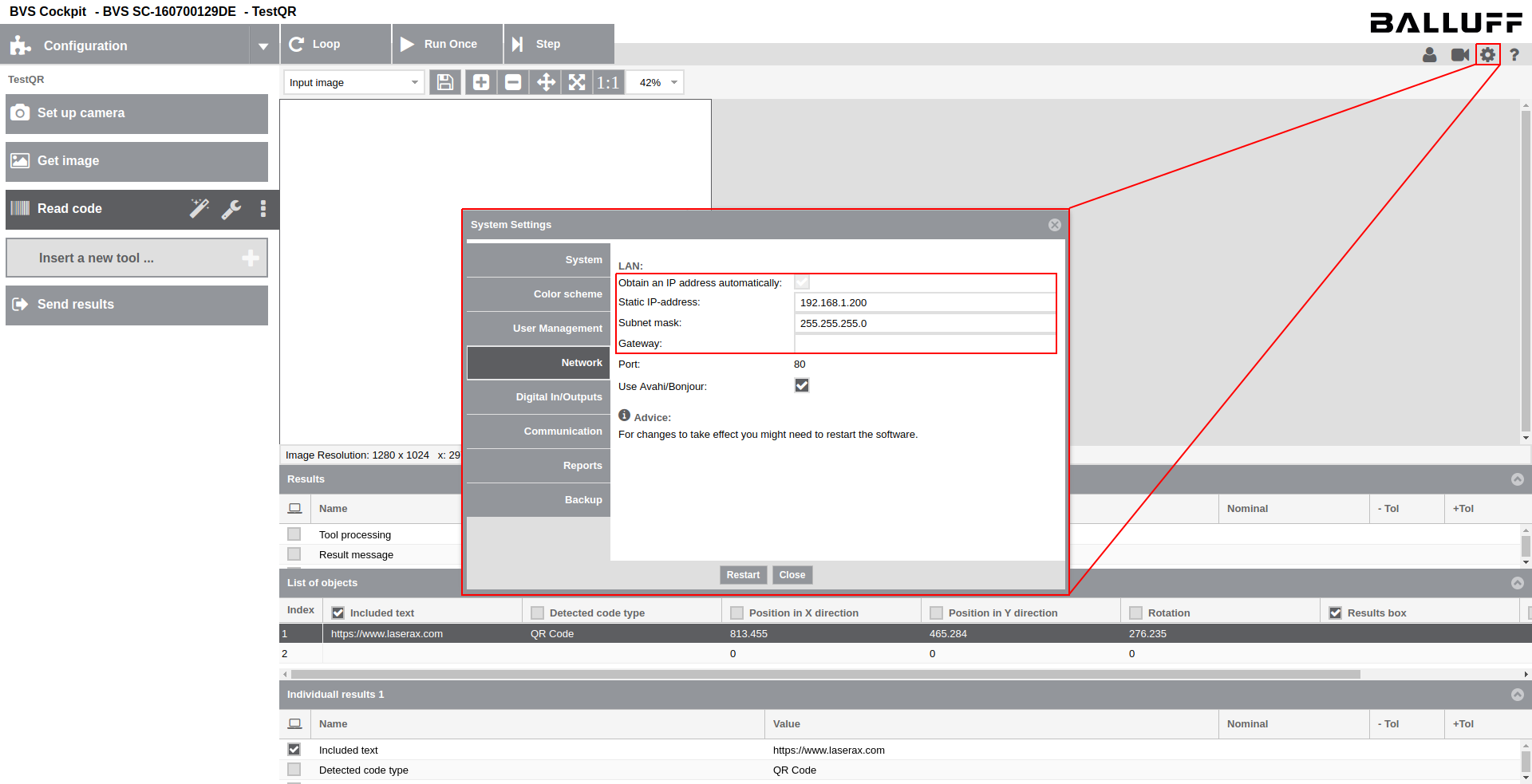
Change the network settings respectively in the camera configurations:
- In the Network section disable the option Obtain an IP address automatically.
- In the Network section configure a static IP and subnet mask reachable by the drag&bot system.
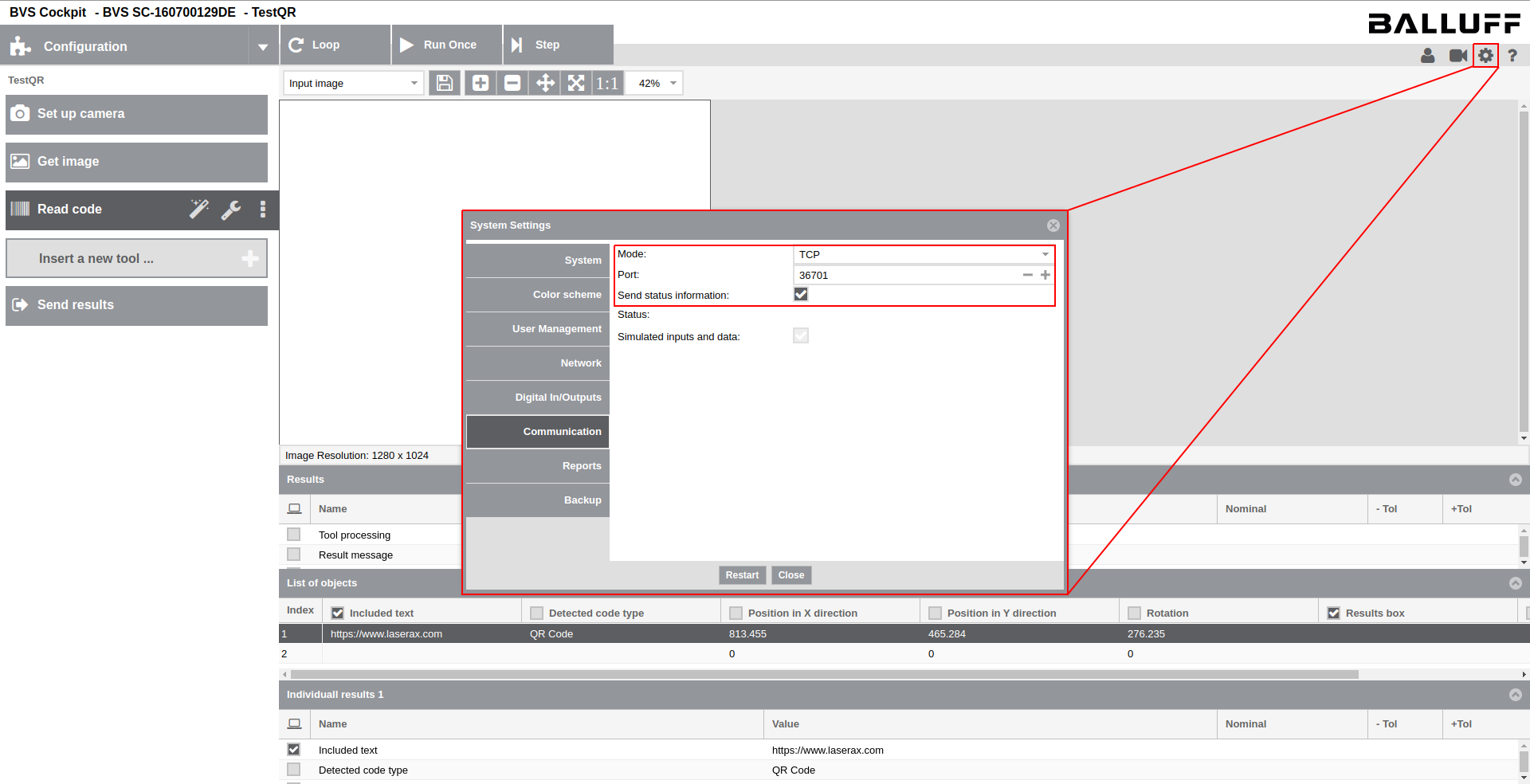
- In the Communication section set the mode to TCP and activate the option send status information.
- In the Communication section note the Port for the configuration later in drag&bot.
Intrinsic calibration in Balluff Smart Camera
Notes and Hints:
- Despite presented differently, certain information of the intrinsic calibration is shared among all Balluff programs. Executing an intrinsic calibration in one program leads to unintentional effects in other programs and might even break them. When a intrinsically calibrated program is duplicated, it keeps the calibration. But a newly created program can not take an existing calibration and needs to be calibrated newly (which then overrides the intrinsic calibration of other programs).
- The position of the intrinsic calibration plate has direct effect on the localization of detected features, as it provides the coordinate system for the camera plane. A shifted calibration plate during an intrinsic recalibration will lead to shifted localization of features to the same extent.
- The intrinsic calibration always needs to be executed again after the camera was moved or the optical setup has changed (adjustment of aperture or focus). As noted above, this has impact on all other programs.
- Its recommended to place the intrinsic calibration plate at the exact same position for each calibration. This avoids unintentional shifts of localizations in other Balluff programs. Use mechanical stops, fixed to the cell, to position the plate in a distinct position.
- For creating programs for object localization after calibrating the camera, existing programs with saved intrinsic calibration should be duplicated.
- If a calibration sheet is printed on paper, this sheet should be fixed to a solid, rigid, rectangular plate. The sheet needs to be fixed as plan as possible to the plate.
Execution:
- Perform the intrinsic calibration as described in the Balluff manual.
Setup in drag&bot
- Select the Balluff SmartCamera component from the list of available components in the drag&bot Component Manger.
- Configure the parameter IP Address for the camera. It has to match with the IP found in the section Network Configuration.
- Configure the parameter Port for the camera. It has to match with the Port found in the section Network Configuration.
- Configure the parameter Calibration Program ID with a program id, which will be used by default for the extrinsic calibration process (see Extrinsic Calibration for more information).

Info
Don't forget to add also the Vision Module Component to your setup.
Extrinsic calibration
Preparation in Balluff Smart Camera
Prepare a calibration program in the Balluff Smart Camera for the extrinsic calibration between the camera and drag&bot. This is a normal camera program with four Find Object task and communication of these four results to drag&bot.
- Create a calibration program on the Balluff Smartcamera, which detects the four patterns and communicates their locations to drag&bot. The program needs to be calibrated intrinsically.
- Use the drag&bot extrinsic calibration plate or print the sheet from here.
- The extrinsic calibration always needs to be executed again after the camera was calibrated intrinsically or moved (in case it is mounted to the cell). In case the camera is mounted to the robot arm, the camera (and robot arm) needs to be placed at the same position for calibration and localizing the production part in the application.
- Its recommended to place the extrinsic calibration plate at the exact same position for each calibration. This avoids unintentional shifts of the localized object. Use mechanical stops, fixed to the cell, to position the plate in a distinct position.
- If the calibration sheet is printed on paper, this sheet should be fixed to a solid, rigid, rectangular plate. The sheet needs to be fixed as plan as possible to the plate.
- The four calibration patterns Origin, A, B and C of the calibration plate have to be detected by the calibration program. It communicates a structure of four Find Object results 'FFFF' to drag&bot. Each pattern, named as "origin", "A", "B" and "C", needs to be sent as one found object in the message.
| Byte Index | Size | Datatype | Description | Linked Example |
|---|---|---|---|---|
| 0 | 20 Bytes | string | structure | 'FFFF' |
| 20 | 1 Byte | bool | success_origin | Find_origin.Tool_processing |
| 21 | 4 Bytes | real32 | x_origin (mm) | Find_origin.Object_1.Position_in_X_direction |
| 25 | 4 Bytes | real32 | y_origin (mm) | Find_origin.Object_1.Position_in_Y_direction |
| 29 | 4 Bytes | real32 | rotation_origin (deg) | Find_origin.Object_1.Rotation |
| 33 | 2 Bytes | int16 | quality_origin (0 to 100) | Find_origin.Object_1.Degree_of_match |
| 35 | 2 Bytes | int16 | quantityfound_origin | Find_origin.Number_of_found_objects |
| 37 | 20 Bytes | string | type_origin | 'origin' |
| 57 | 1 Byte | bool | success_a | Find_a.Tool_processing |
| 58 | 4 Bytes | real32 | x_a (mm) | Find_a.Object_1.Position_in_X_direction |
| 62 | 4 Bytes | real32 | y_a (mm) | Find_a.Object_1.Position_in_Y_direction |
| 66 | 4 Bytes | real32 | rotation_a (deg) | Find_a.Object_1.Rotation |
| 70 | 2 Bytes | int16 | quality_a (0 to 100) | Find_a.Object_1.Degree_of_match |
| 72 | 2 Bytes | int16 | quantityfound_a | Find_a.Number_of_found_objects |
| 74 | 20 Bytes | string | type_a | 'A' |
| 94 | 1 Byte | bool | success_b | Find_b.Tool_processing |
| 95 | 4 Bytes | real32 | x_b (mm) | Find_b.Object_1.Position_in_X_direction |
| 99 | 4 Bytes | real32 | y_b (mm) | Find_b.Object_1.Position_in_Y_direction |
| 103 | 4 Bytes | real32 | rotation_a (deg) | Find_b.Object_1.Rotation |
| 107 | 2 Bytes | int16 | quality_b (0 to 100) | Find_b.Object_1.Degree_of_match |
| 109 | 2 Bytes | int16 | quantityfound_b | Find_b.Number_of_found_objects |
| 111 | 20 Bytes | string | type_b | 'B' |
| 131 | 1 Byte | bool | success_c | Find_c.Tool_processing |
| 132 | 4 Bytes | real32 | x_c (mm) | Find_c.Object_1.Position_in_X_direction |
| 135 | 4 Bytes | real32 | y_c (mm) | Find_c.Object_1.Position_in_Y_direction |
| 140 | 4 Bytes | real32 | rotation_c (deg) | Find_c.Object_1.Rotation |
| 144 | 2 Bytes | int16 | quality_c (0 to 100) | Find_c.Object_1.Degree_of_match |
| 146 | 2 Bytes | int16 | quantityfound_c | Find_c.Number_of_found_objects |
| 148 | 20 Bytes | string | type_c | 'C' |
The complete message has a length of 168 Bytes.
- The patterns should be teached in a way, that the center of the detected object is at the intersection point of the cross for each pattern.
This program  can serve as template but its necessary to calibrate it intrinsically and reteach the patterns.
Preparation in drag&bot
- The selected tool in drag&bot needs to be the same as later for the actual application.
- The orientation of the calibration plate represents the zero degree orientation of the localized object later.
Before the extrinsic calibration process is executed, its recommended to prepare the four calibration poses Origin, A, B, C in drag&bot for better access in the wizard and repeatability in case of recalibration.
- Create and teach four Quick Access Moves for the corner positions. Configure the same tool, which you want to use in the application.
Execution of extrinsic calibration
For calibrating the Balluff Smart Camera extrinsically with drag&bot, follow the extrinsic calibration procedure.
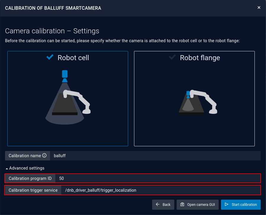
When choosing whether the camera is mounted to the cell or to the robot flange, ensure that the Calibration program id is correct and the Calibration trigger service is set to '/dnb_driver_balluff/trigger_localization' at Advanced settings.
Use the Quick Access Moves to move the robot to the three positions.
Teaching production part
- Duplicate the extrinsic calibration program to keep the contained intrinsic calibration.
- Do not calibrate the program intrinsically again. If you have to, for some reason, repeat the extrinsic calibration after you calibrated intrinsically and before you teach the part.
- Adjust the communicated results according to the structures defined here.
- Teach the part, placed in the zero degree orientation, as described in the Balluff Manual.
- Use the Function Block Balluff - Localize Object to localize the part in the program.