Fanuc R-30iB Controller Setup
Important
The software options R648 "User Socket Msg" and R632 "KAREL" must be installed on the robot controller.
Info
The drag&bot driver is also compatible with the R-30iB Mate and R-30iB Plus variants.
Further it is only compatible with the following Fanuc controller software versions: V9.10, V9.00, V8.36. In addition the older drag&bot release (before bundle 3.5.0) is also compatible with V8.33, V8.30, V8.23, V8.20, V8.13, V8.10. The drag&bot system was tested only with the Fanuc controller V9.40.
Downloads
The required controller files can be downloaded from here: Downloads
Fanuc Teach Pendant Introduction
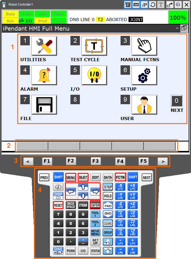
The Fanuc teach pendant consists of several areas, where the most relevant are described in the following:
- The display main area (1) is the most important area. Here all menus and lists are displayed.
- At the bottom of the display is the software button bar (2). There are always up to five buttons with dynamic meaning.
- Below the software button bar is the hardware button bar (3) with labels 'F1', 'F2', 'F3', 'F4' and 'F5'. These buttons are directly connected to the software button bar, so F1 always "presses" the first software button and so on. The buttons '<' and '>' can change the button choice, if there are more buttons than can be displayed.
-
The main input device are the buttons (4). In the figure shown below the most important buttons are marked red:
 switches to the main menu, which is shown in the figure below.
 switches to the list of available programs.
 resets any error or message shown in the top area of the display main area.
Fanuc controllers use multipages for their menu navigation. If a described entry does not appear at the first page, please search also the following pages with the NEXT or next page menu entry.
All descriptions assume that the HMI Full Menu view is selected on the Fanuc teach pendant. You can change to the HMI Full Menu view by pressing the ![]() button and toggle the QUICK/FULL MENU option.
button and toggle the QUICK/FULL MENU option.
Find the controller IP
- Press the button , enter the SETUP menu and there the Host Comm section.
- Select the protocol TCP/IP and press the button DETAIL at the bottom bar.
Configure the controller for drag&bot
Configuration of the Fanuc R-30iB controller is divided into two steps. At first the drag&bot controller files have to be transferred to the controller. Secondly a specific configuration has to be performed in the controller system parameters.
Info
Pleace note that the setup process is only confirmed to be successful with a fresh controller with no other additional software options or hardware than described above. Controllers, which do already have an existing setup or extended hardware, might need further or different adjustments than described here.
Also it's strongly recommended to backup your controller state before performing any changes.
Enable the required user tasks and register ranges
The drag&bot controller program uses
- four User Tasks and one Motion Task,
- the Fanuc Registers 190 to 300,
- the Fanuc Position Registers 100 to 105,
- the Fanuc IO Flags 99 to 115 and
- the Fanuc communication servers 3 and 4.
for the internal processing. The registers and flags should not be used for other purposes or the values might be overwritten by the drag&bot controller program. Before installing the drag&bot controller program ensure to enable the registers in the Fanuc controller settings.
-
First check if there is a need to extend the available values. After startup of the controller press the soft button
 and press the TYPE button at the bottom bar and select 1 Registers. Note the numbers of the selected and available registers at the top right (e.g. "1/200"). If the second number is below 300 the registers need to be extended. Repeat the process for the pose registers. Press the TYPE button at the bottom bar and select 2 Position Reg. Note the numbers of the selected and available position registers at the top right (e.g. "1/100"). If the second number is below 105 the position registers need to be extended.
 -
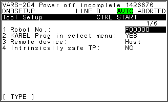
In order to extend the registers and position registers restart the controller with a controlled start. Shut down the controller and restart it while pressing the F1 and F5 buttons. After restart the teach pendant will open a special configuration menu:
- Press the soft button to enter the menu entries.

- Select the entry 0 -- NEXT -- at the bottom with the
 buttons and change to the next page with the
  button.
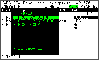
- Select the entry 1 PROGRAM SETUP at the top with the buttons and enter it with the button.
-
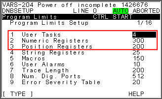
Select the entry 1 User Tasks and press the
button to configure the entry. Configure a value of at least 4 user tasks. Apply the change by pressing the button. -
Select the entry 2 Numeric Registers and press the
button to configure the entry. Configure a value of at least 300 registers. Apply the change by pressing the button. -
Select the entry 3 Position Registers and press the
button to configure the entry. Configure a value of at least 105 registers. Apply the change by pressing the button. -
After adjusting all parameters, apply the changes by restarting the controller.
Load the program files
- Download and unzip the correct drag&bot Fanuc controller program files from here.
- In the unziped download file you will find several directories, which indicate the Fanuc controller software version. You need the files in the directory corresponding to your controller software version.
- To determine your controller version at the teach pendant press the button, enter the STATUS menu and there the Version ID section. The entry Software Edition No. describes the Fanuc controller software version, e.g. V8.20P/31.
- Copy all files ending with .pc and .tp of the matching directory to a USB pendrive. Just the first part of the software version is relevant, e.g. V8-20.
- Insert the USB pendrive at the teach pendants USB port.
- Press the button and select the FILE menu and there the File section.
- Set the source device to USB by pressing the UTIL button at the bottom bar and select Set Device. Select the option USB on TP (UT1:).
- Select the 'all files' entry and confirm with the button.
- Transfer all files copied on the USB pendrive to the controller by selecting the file with the cursor arrows and press the LOAD button at the bottom bar. Confirm each transfer with YES.
- Check, whether all files were copied. Press the button. All program files should be listed. Note that there might be additional files than copied from the USB-Stick.
Setup the controller configuration
- Starting the drag&bot setup program can be done in automatic mode or manual mode.
- Start the R-30iB controller.
- To start the drag&bot controller setup program press the button and select the DNB SETUP program. Press to choose the program.
- In automatic mode: press the Green Start Button at the controller to start the controller program.
- In manual mode: enable the teach pendant with the enable switch on the top left corner. Switch to continuous mode by pressing the
 button that the respective status indicator "Step" is green. Press the
  button with the
  soft button to start the configuration.
 - At the teach pendant you can watch outprints of the setup program when switching to the user view. To change there press the button and select the USER menu.
- Restart the controller.
Setup for drag&bot Studio
- Please select Fanuc R30iB Robot from the dropdown menu in the drag&bot Component Manger.
- Configure the parameter IP for your setup. It has to match with the IP found in the section Find controller IP.
- Configure your Robot Model for visualization. If your model is not listed, you can use the "-" entry to work without visualized robot model.
- Eventually adjust the digital inputs and outputs. For this see the section Setup Digital I/Os.
Setup Digital I/Os
To use Digital I/Os with drag&bot they need to be available in the robot controller and also need to be configured in the drag&bot Component Manager.
Check which Digital I/Os are available in the controller
- Press the button , enter the I/O menu and there the Digital section.
- A list of Digital Inputs or Outputs will appear. You can switch between Input and Output list with the button IN/OUT at the bottom bar.
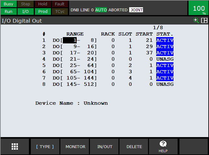
- To see which Digital Inputs or Outputs are available change to the configuration with the button CONFIG at the bottom bar.
- Here you can see a list of ranges of inputs or outputs. Each entry defines a range from where to where the range is defined (Column RANGE). Further it is configured where the hardware is placed in controller providing this I/Os (Columns RACK, SLOT, START). At last it is defined, whether the range is activated (ACTIV) or deactivated (UNASG) indicated in the column STAT. The additional hardware and software options defines, which ranges are activated or not.
- Change nothing in the configuration, just note the ranges for Inputs and Output, which are activated. Just activated I/Os can be used in drag&bot.
Example: In the figure below the Digital Outputs 1 to 20 and 25 to 144 are activated.
Configure the Digital I/Os in the Component Manager
-
Based on the activated Digital I/Os in the Controller you can choose the Digital I/Os to be usable in drag&bot.
-
Individual digital I/O numbers and digital I/O ranges are allowed as shown in the following example: "1-8,12,17-24" In total 128 I/Os in 10 ranges each can be defined at maximum. A range is defined by a start pin and an end pin. Also just one pin can be defined (single I/Os count as one range, e.g. the example has 3 ranges with 17 digital inputs). If no digital input/output should be defined, enter "-".
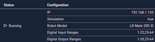
- Setup your choosen configuration in the Component Manager. If the configuration was not accepted, the status changes to Stopped.
Example: In the figure below the Digital Outputs 1 to 20 and 25 to 64 are activated, based on the example from above. This are 60 pins in total in two ranges.
Additional Hints
Encoder Batteries
Always ensure that the robot encoder batteries do not completely discharge. Otherwise a re-mastering of the robot might be necessary. For more information see the R-30iB Controller Maintenance Manual and the R-30iB Controller Software Error Code Manual.