KRC5 Driver Installation
Driver Installation: Controller-Side
Requirements
- The KUKA.EthernetKRL V3.2.4 software package must installed in the robot controller. This package has an extra cost so that it has to be bought from KUKA robot manufacturer. Please follow the installation instructions received within the software package. The drag&bot is only tested with version 3.2.4.
- You must log in as an Expert or Administrator to make the required configuration, in this document. Your log in can expire after a time or when you change to automatic operation mode. In this case you need to log in again to continue the robot configuration.
- A PLC with Digital Inputs/Outputs module.
- PC Connected to the KUKA Controller Ethernet connection labelled XF5 in KRC5 micro controller.
- The PC is the TCP client and the robot is the server.
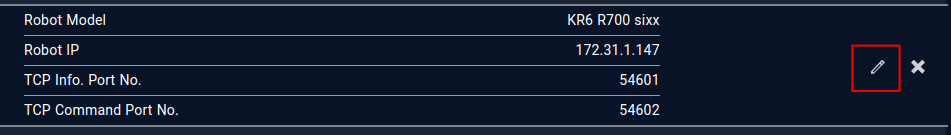
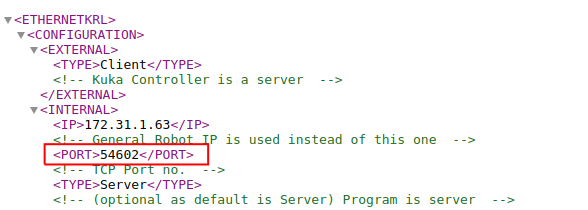
- The TCP/IP ports numbers should be
54601and54602unless it's changed in the dnb_client_recv.xml and dnb_client_send.xml files. - If you need to change the TCP/IP ports numbers, then please change it in the dnb_client_recv.xml and dnb_client_send.xml files before uploading it into the controller.
Downloads
The required controller files can be downloaded from here: Downloads
Notes
Refer to the general notes related to the controller driver before starting Click here.
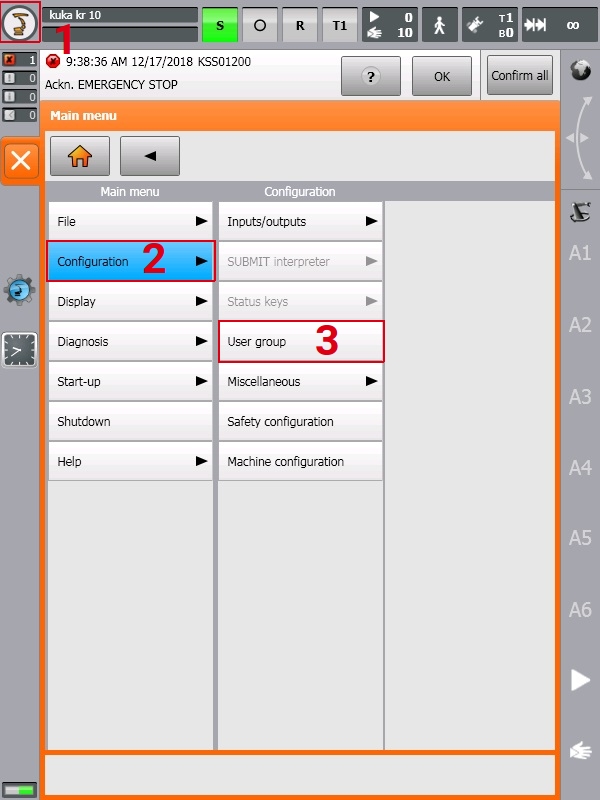
Log in as Expert
-
on the top left side of the HMI screen, then and .
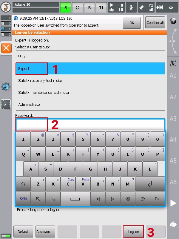
-
then enter the password (please contact KUKA, if unknown) and .
Minimize HMI and access to windows OS
Prerequisites
- Robot in T1 mode.
- on the top left side of the HMI screen, then and then .
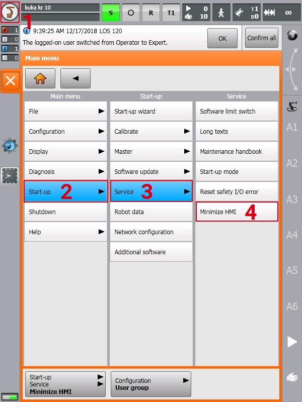 Now the window OS screen will be shown.
Robot IP
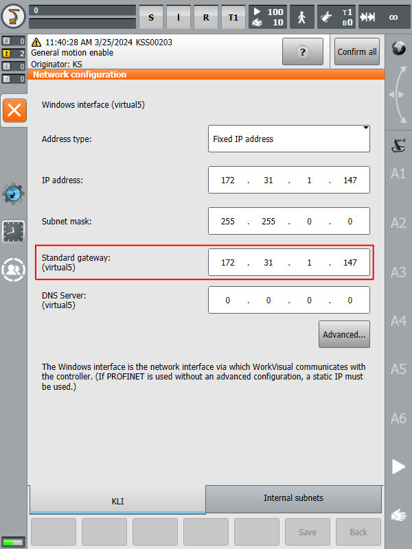
You can find your robot's IP to be used in the drag&bot software by following the steps below:
-
on the top left side of the HMI screen, then and .
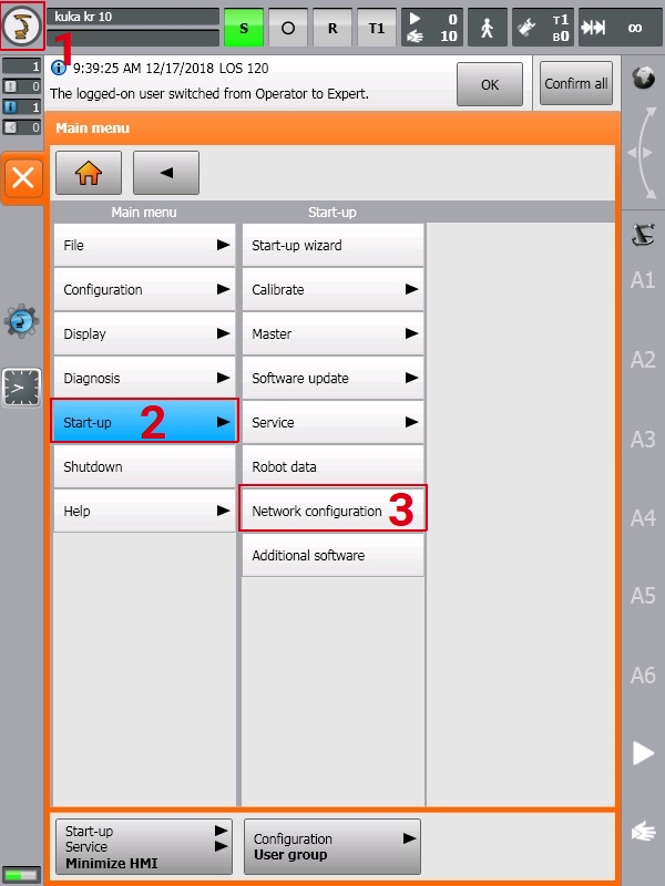
-
The robot IP is shown in the field "Standard gateway:(virtual5)".
External PLC controlling
In order to be able to automatically start the controller driver, the robot needs to work with the Automatic External mode. This requires an additional wiring to a PLC to control the driver/robot startup.
Signals configuration
In order to control the robot in automatic external mode, signals below need to be mapped to the robot's digital IOs :
| Signal | Description | Type |
|---|---|---|
| $EXT_START | Program start | DI |
| $MOVE_ENABLE | Robot Motion Enabled | DI |
| $CONF_MESS | Robot's Error Acknowledgment | DI |
| $DRIVES_OFF | Robot's Drives Off (Reverse signal) | DI |
| $DRIVES_ON | Robot's Drives On | DI |
| $I_O_ACT | Activate Automatic External Interface | DI |
| $RC_RDY1 | Controller is Ready | DO |
| $ALARM_STOP | E-Stop circuit is closed | DO |
| $USER_SAF | Operator Safety circuit is closed | DO |
| $PERI_RDY | Robot Drives are ready | DO |
| $I_O_ACTCONF | Automatic External Interface is ready | DO |
| $STOPMESS | Collective fault | DO |
| $ALARM_STOP_I | Internal E-STOP circuit is closed | DO |
| $$PRO_ACT | Program is active | DO |
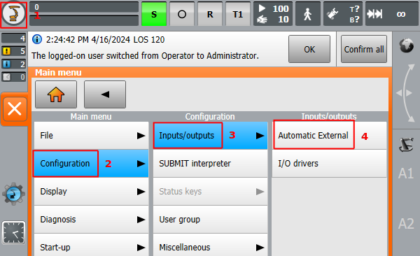
-
on the top left side of the HMI screen, then and then .
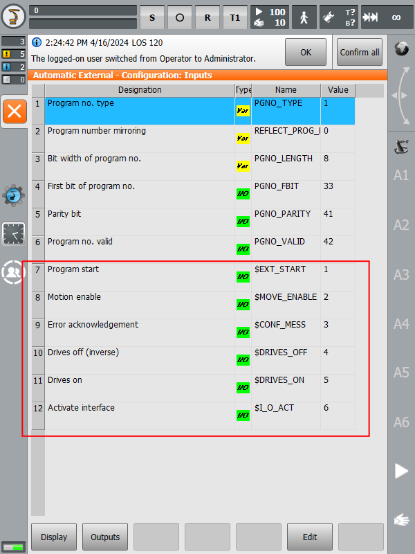
-
The first opened page are the robot's input signals. The signals marked with the red (picture below) should be linked to the robot's digital inputs. Please note that these digital inputs numbers are the soft IOs which should be linked to the actual hard IOs using the KUKA WorkVisual, for this please refer to the WorkVisual documentations.
-
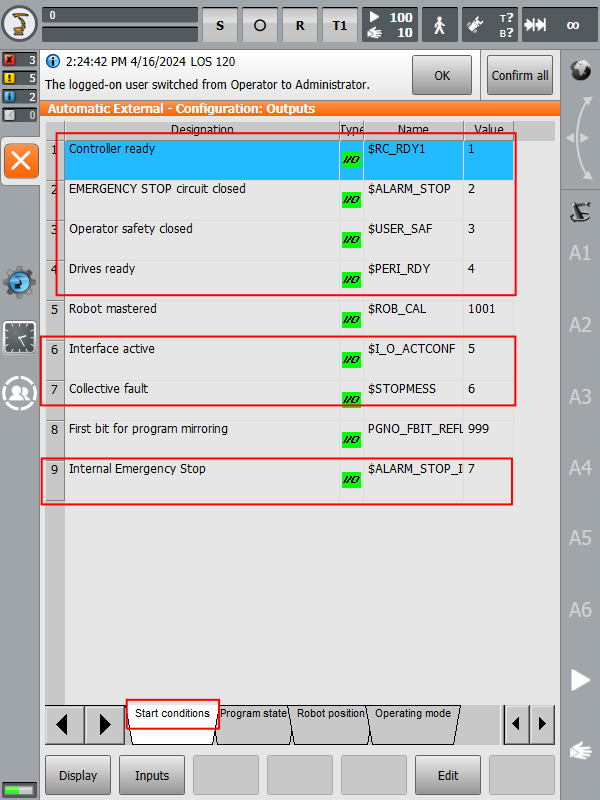
Open the Outputs tab at the bottom on the screen to configure the output signals. On the Start conditions, the signals marked with the red (below picture) should be linked to the robot's digital outputs. Please note that these digital outputs numbers are the soft IOs which should be linked to the actual hard IOs using the KUKA WorkVisual, for this please refer to the WorkVisual documentations.
-
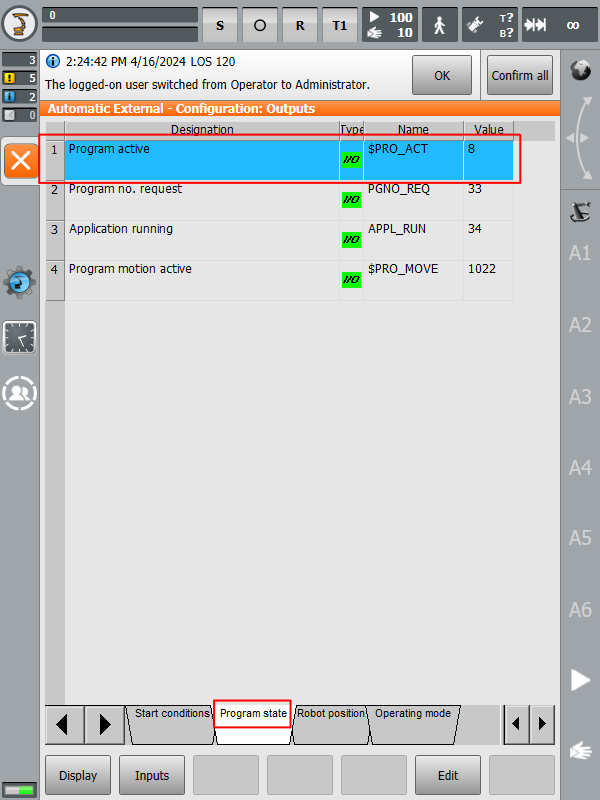
On the Program state conditions, the signal marked with red (picture below) should be linked to the robot digital output. Please note that this digital output number is the soft IO which should be linked to the actual hard IO using the KUKA WorkVisual, for this please refer to the WorkVisual documentations.
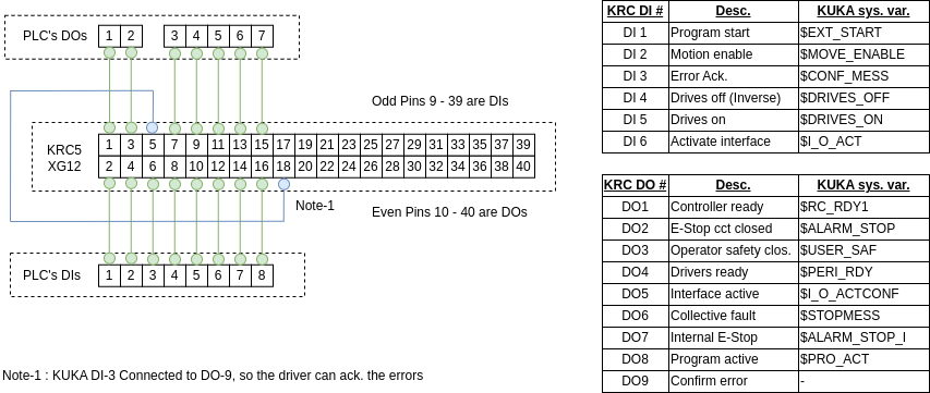
Wiring diagram
Notes
- The digital IO numbers in the diagrams below are just an example and the final IO numbers should be based on your system design.
- Please note that error acknowledgment signal is linked to the soft digital output number 9 ($OUT[9]). You can assign a different IO number under the controller file dnb_sps_send.dat, where you can assign a different IO number to the variable GLOBAL SIGNAL ERROR_ACK_DO $OUT[9].
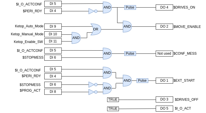
PLC Logic
Notes
- The digital IO numbers in the diagrams below are just an example and the final IO numbers should be based on your system design.
- Please note that error acknowledgment signal is linked to the soft digital output number 9 ($OUT[9]). You can assign a different IO number under the controller file dnb_sps_send.dat, where you can assign a different IO number to the variable GLOBAL SIGNAL ERROR_ACK_DO $OUT[9].
drag&bot Driver Installation
Step A: driver files
Prerequisites
- Robot in T1 mode
- You should be logged in as an Expert or Administrator in order to see and access the USB flash drive.
-
Transfer the drag&bot files to a USB flash drive, then connect it to the KRC5 USB port.
-
In the Navigation window, navigate to the drag&bot files on the USB flash drive, then select
dnb_main.srcanddnb_main.datfiles then and .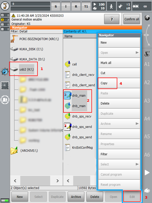
-
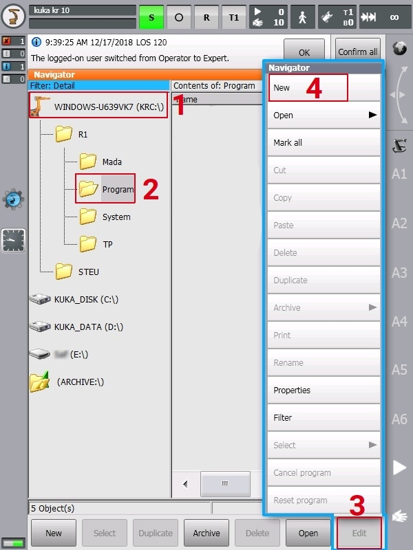
In the Navigation window open the Program folder under the path KRC:\ -> R1 -> Program and create a new folder by then , give the new folder the name dnb .
-
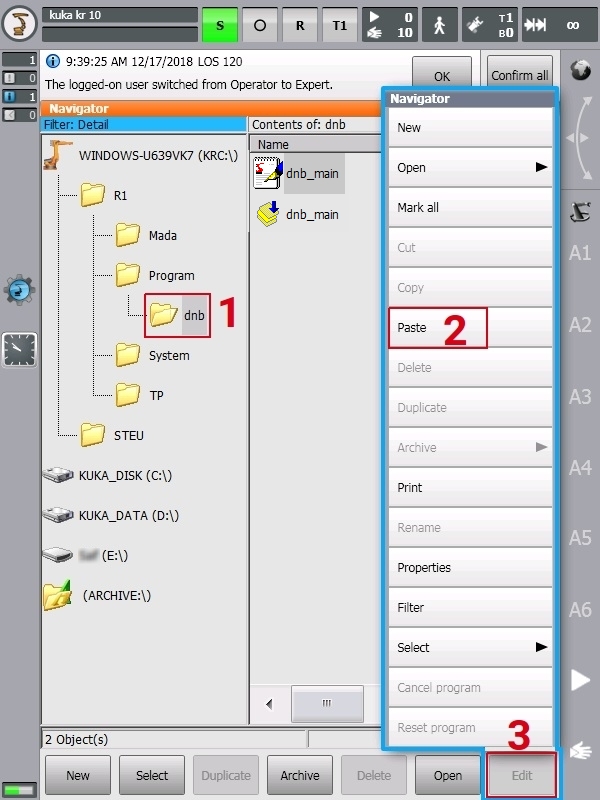
Open the dnb folder, then . Now the dnb_main.src and dnb_main.dat files will be copied into the dnb folder.
-
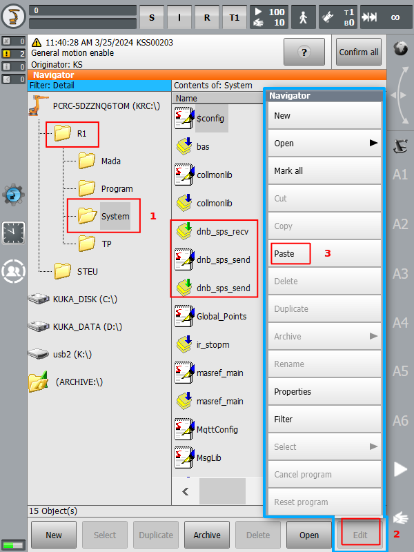
In the Navigation window, navigate to the drag&bot files on the USB flash drive, then select
dnb_sps_recv.subanddnb_sps_recv.datanddnb_sps_send.subfiles then and .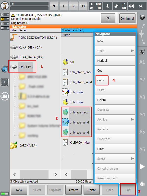
-
Navigate to the path R1->System, then . Now the dnb_sps_recv.sub and dnb_sps_recv.dat and dnb_sps_send.sub files will be copied into the System folder.
-
Make a backup copy of your cell.src file. In case you use cell.src to start another controller programs, then implement the code from the drag&bot cell.src into your controller cell.src file. and don't follow steps 9 & 10 below.
-
In the Navigation window, navigate to the drag&bot files on the USB flash drive, then select
cell.srcfile then and .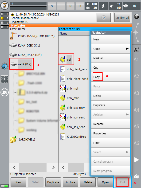
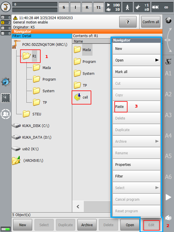
-
Navigate to the path R1, then . Now the cell.src file will be copied into the R1 folder.
Step B: communication/error acknowledgement files
Prerequisites
- Robot in T1 mode
- You should be logged in as an Expert or Administrator in order to see and access the USB flash drive.
Note
- The TCP/IP communication use ports numbers '54601' & '54602' by default, if you wish to use another port then please change the ports numbers in the files dnb_client_send.xml and dnb_client_recv.xml before you upload it to the controller.
-
Minimize the HMI to access the windows OS. Click here to see how.
-
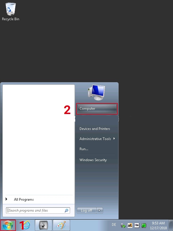
From the windows start menu .
-
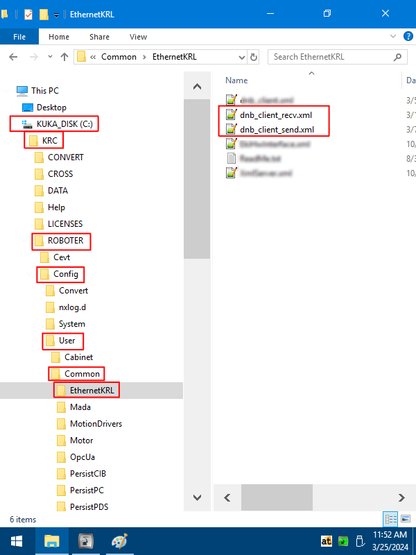
Navigate to the drag&bot files on the USB flash drive, select and copy the dnb_client_recv.xml and dnb_client_sen.xml files and paste the two files into the path C:\KRC\ROBOTER\Config\User\Common\EthernetKRL
-
Navigate to the drag&bot files on the USB flash drive, select and copy the KrcExtConfMsg.xml file and paste the file into the path C:\KRC\ROBOTER\Config\User\Common
Step C: auto starting configuration
Prerequisites
- Robot in T1 mode
- You should be logged in as an Expert or Administrator.
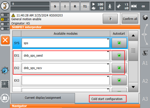
-
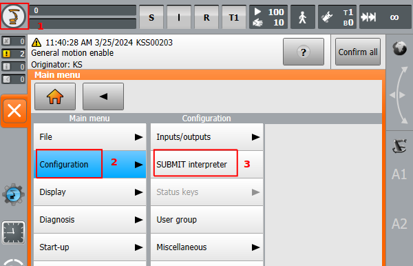
on the top left side of the HMI screen, then and .
-
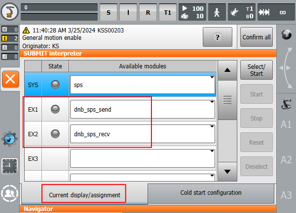
tab, then select dnb_sps_send under EX1 and dnb_sps_recv under EX2.
-
tab, then select dnb_sps_send under EX1 and dnb_sps_recv under EX2 and ensure that Autostart is activated for both tasks.
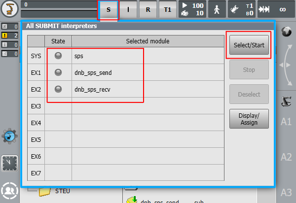
-
Click on the S symbol at the top of the screen then click on the Select/Start.
Controller Restart
Prerequisites
- Robot in T1 mode
- You should be logged in as an Expert or Administrator.
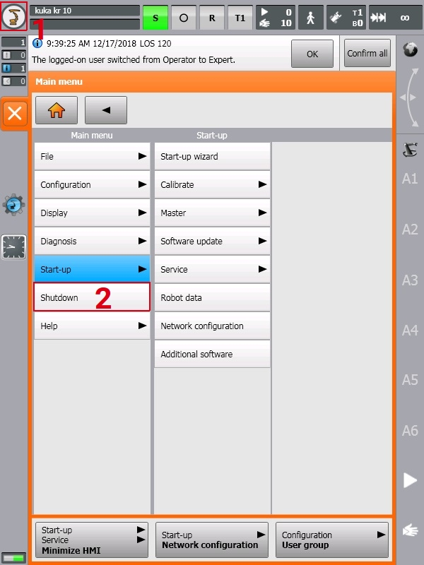
-
on the top left side of the HMI screen then .
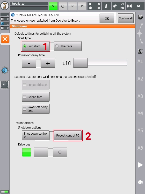
-
and (if it's requested when you saved the IP configuration) then ". Now wait till the Controller restarted.
Now the robot controller side installation is finished. You can continue with the Drag&bot robot configuration steps.
drag&bot Setup
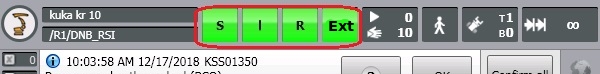
- Change the robot mode to External using the KUKA teach pendant, the S, I, R, and Ext fields should be now with the green color.
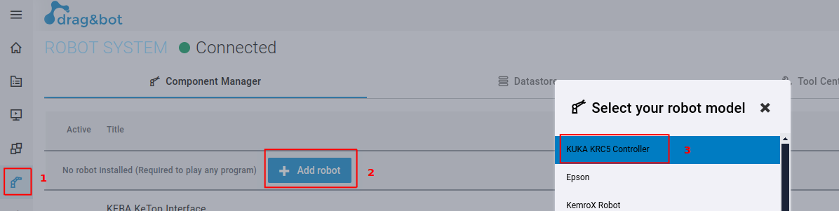
- In the drag&bot system, open the Component-Manager, then click on Add robot and select KUKA KRC5 Controller.
- Edit the robot model, IP, and ports numbers if changed.