Vision
1. Preconditions and relevant information
Vision Module Component
Requirements
When using non-smart cameras make sure to add the respective camera component and the Vision Module component to your component setup. This is required to show the camera image in the drag&bot Studio and perform the calibration.
Camera mounted at robot flange / tool
Requirements
- The camera must be mounted attached to the robot flange or to the tool, as long as it moves together with the robot tool. Camera doesn't need to point in the same direction of the robot tool, but it should be as near as possible to minimize the required orientation change to reach target positions.


- The tool tip (TCP) must be able to be moved from any localization position (left) to the localized pose through Offset Move. Depending on the camera and TCP position this movement can be difficult due to geometry and joint limitations, therefore we recommend to point the camera in the same direction of the robot tool to minimize the Offset Move.

- The tool tip (TCP) must be correct configured in drag&bot and selected before starting calibration process. The calibration resulting after the calibration process is only correct for the current tool selected at the moment of calibration.
- Using a calibration spike is not possible due to a current algorithm limitation. Currently the position of the end-effector (tool tip) must be placed always onto the calibration sheet positions. If not, the resulting calibration will be incorrect. The only possibility to use a calibration spike is manually calculate the frame transformation between tool and calibration spike and then modifiy accordingly the saved values in calibration file for reference_origin, reference_a and reference_b. This will require a good knowledge in frame transformations.


- Tool tip Z coordinate must point down for a correct object rotation localization. If this is not the case, object rotation localization won't work but yet position localization as long as object rotation localization angle is fixed to 0. The reason is that if the camera detects an object rotated 20°, then it will apply -20° rotation directly in TCP Z.

- The camera should see the calibration sheet as undeformed as possible during calibration process. Therefore should be perpendicular to the paper. Inaccuracies will be compensated through homography transformation.
- Tool orientation cannot be changed between Origin, A and B positions in calibration sheet.

Camera mounted at cell
Requirements
- The camera must be fixed static to the robot cell. Moving the robot won't modify camera position.
- The same tool center point position and orientation constraints apply as when mounted at robot flange / tool.

2. Intrinsic calibration
Download
- For the calibration the following checkerboard needs to be printed: DOWNLOAD

- Depending on the FOV of the camera the scale factor of the printer should be set to 25% or higher.
This video shows how the camera intrinsic calibration is done in drag&bot.
- Open the Component-Manager
- Add the component Vision Module and a supported camera e.g. Basler.
- Start the calibration by clicking the grid symbol in the component.
- Select Intrinsic calibration.
- Please measure the square size of a single square on the checkerboard and enter it in millimeters.
- At Advanced settings, you can change the calibration name and change the camera image topic when required.
- Start moving the calibration sheet in front of the camera in different positions and orientations till the calibration is done.
- Wait until the intrinsic calibration is calculated (approx. half a minute).
- Now open the settings of the installed camera e.g. Basler Camera and in the field Intrinsic calibration name enter the same name as set in the advanced settings at the beginning of the calibration.
- Apply the changes.
- Now the intrinsic calibration is ready and the extrinsic calibration can be executed. In the extrinsic calibration the rectified topic is now available e.g. /pylon_camera_node/image_rect (see next step)
Important
It is important to use the rectified topic name e.g. /pylon_camera_node/image_rect in every function block which is used for computer vision.
3. Extrinsic calibration
This video shows how the calibration of a camera mounted to a robot flange is done in drag&bot.
Execute the calibration with the following steps:
- Open the Component-Manager
- Add the component Vision Module and a supported camera e.g. Basler.
- Start the calibration by clicking the grid symbol in the Basler component.
- Click through the calibration steps. The Calibration Sheet can also be downloaded here. DOWNLOAD
- In the step Camera calibration - Settings choose the rectified topic under Advanced Settings
Important
For later localizing of parts with rotations it is important that the Tool TCP Z direction is centered on the calibration symbols and pointing down to the calibration board. Vision localization Function Blocks use this Tool Z direction for rotating the camera according to the localized part rotation.
Important
The calibration is done for a specific localization distance and camera tilt. The camera needs to keep always the same orientation to the localization surface. At best note the pose which you are doing the calibration for. Usually when your calibration sheet is placed parallel to the robot coordinate system you would note the Z-Axis value and camera tilt.
4. Application
After the calibration is done you can start write your application.
4.1. Basics
Working with files or picture in drag&bot needs special knowledge. If you want to use files inside the drag&bot Runtime docker container you need to place your files into a special folder location. Create the location when not existent. Open the terminal:
mkdir -p ~/.dnb/data/vision
cd ~/.dnb/data/vision
~/.dnb/data/vision.
4.2. Image Dataset
As example patterns to detect use the following images:
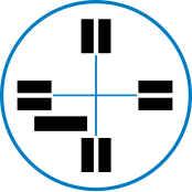
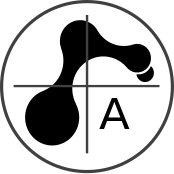
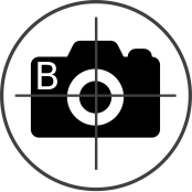


Download by right-click and 'Save image as...'
4.3. Function Blocks
Open the Function Block Manager and see which function blocks you can add to your basic library.
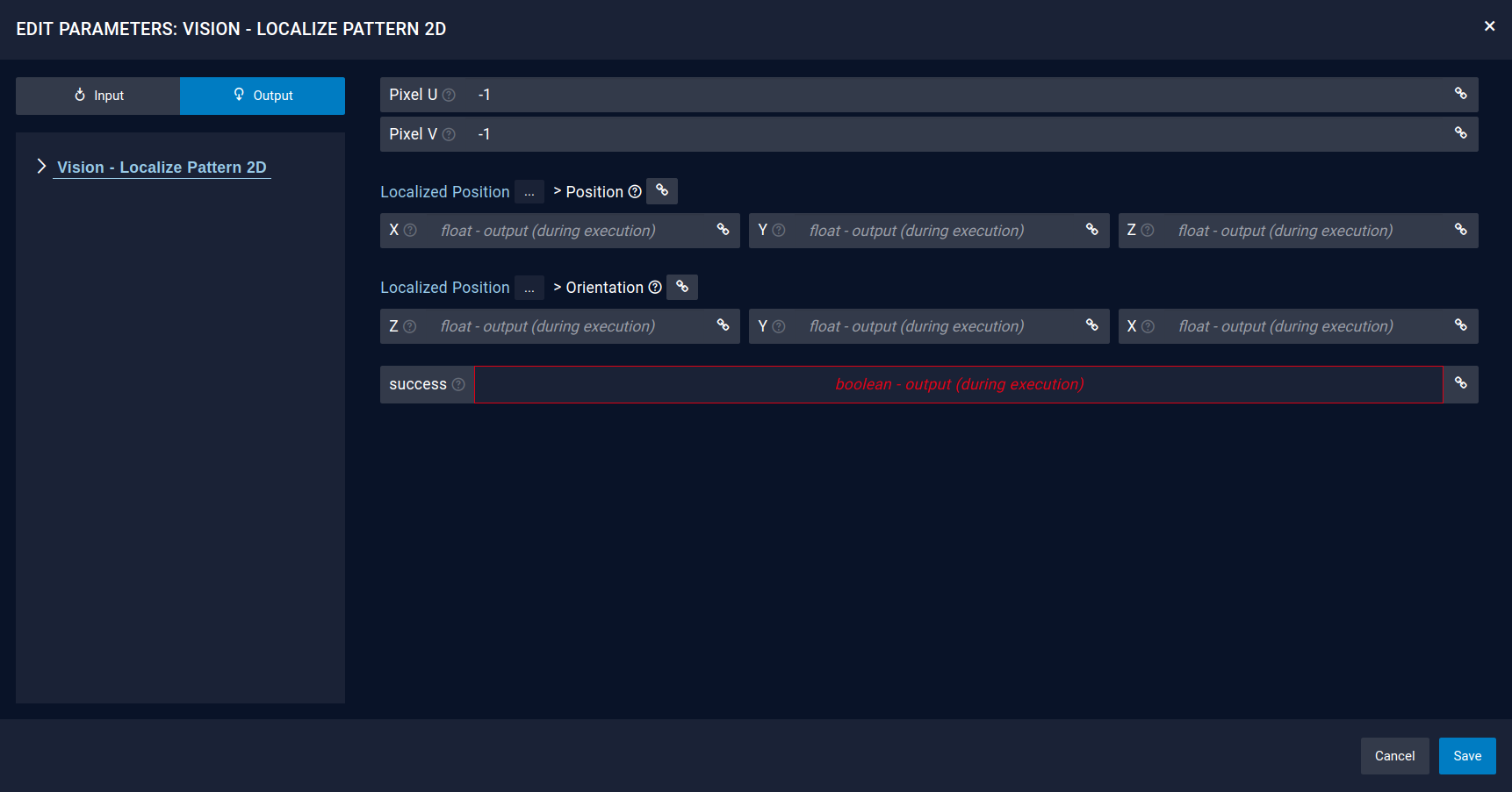
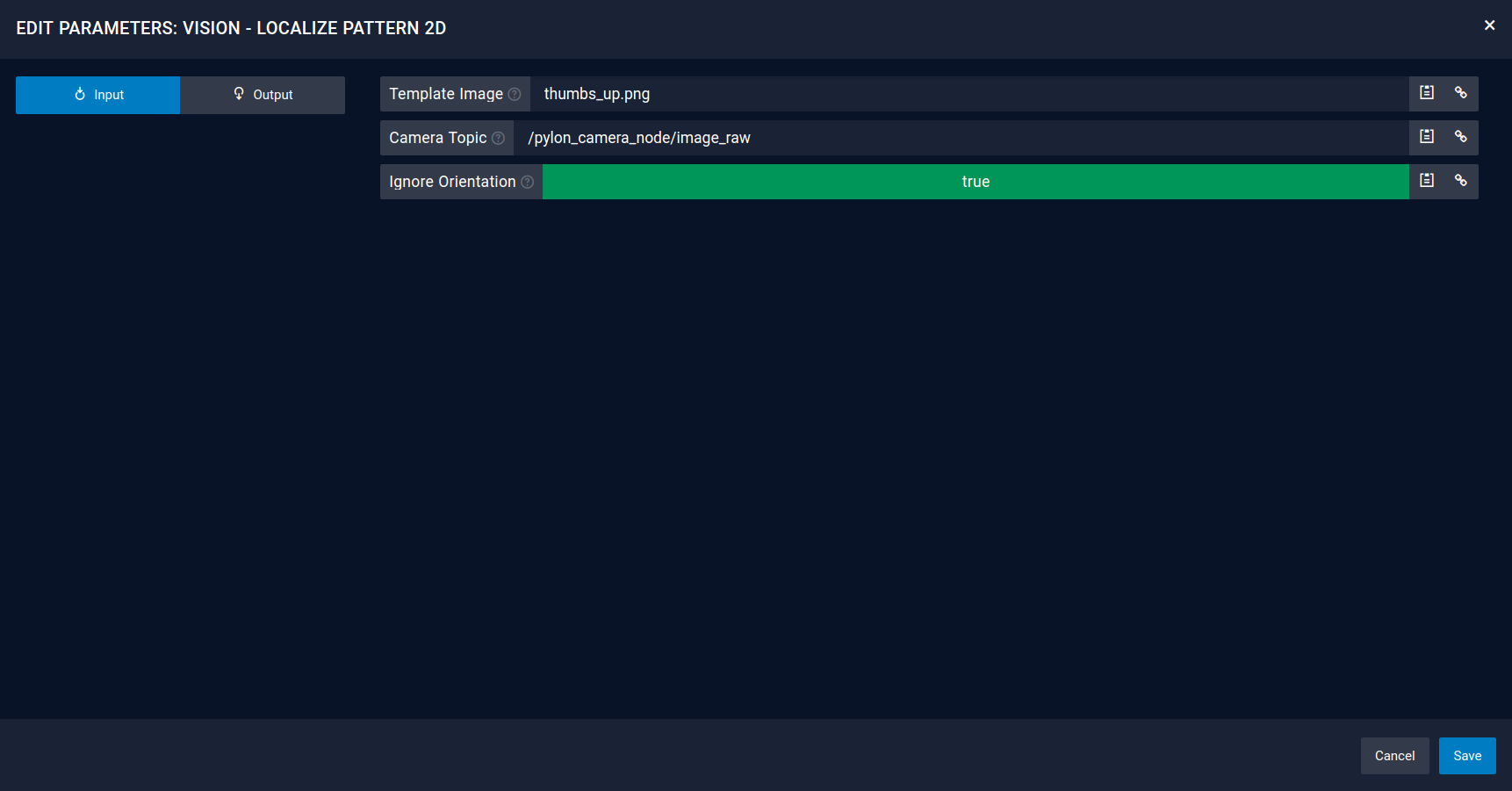
4.3.1. Vision - Localize Pattern (2D)
The localize pattern function block will detected a pattern with OpenCV methods. Therefore a picture file should be given as an input and a camera topic. As a result the function block will return a success boolean and a pose to link. Moreover you can also use the returned pixel coordinates to do an individual calculation.
Important
In the Camera Topic choose the rectified topic name for using the detection on the intrinsically calibrated image
Important
Using the Vision - Localize Pattern (2D) detects the pixel center of an image. That means the robot is moving to the center of the image. Make sure to center your image when creating own patterns.
Inputs
Outputs