Setup Driver
Setup: Controller-Side
Requirements
- You need a KUKA Sunrise Workbench application installed on a Windows computer. The application is provided by KUKA together with the robot.
- The Windows computer needs to be connected to the robot through Ethernet cable directly or via switch.
- Network Ethernet port 30000 must be opened in the robot controller. This is automatically done in newer robot revisions but it stills need to be manually done in older versions. Detailed process can be found at the end of this document.
Downloads
The required controller files can be downloaded from here: Downloads
Warning
Please note that the KUKA Sunrise software has many releases, which are not compatible with each other. If you use a different release than the release that used before to configure/program the controller or the same release but with different loaded optional packages, then probably your sunrise will not be able to communicate or find the Controller in the network.
We recommend to have the same version of Sunrise in your computer and in the robot controller, or update the controller to the latest version corresponding to the one in your computer.
The drag&bot runtime requires installing a new robot program DragAndBotDriver in the robot controller as well as some additional files and configuration. Therefore the following steps are necessary:
- Import project from robot controller to Sunrise Workbench or create a new one if none is available in the controller.
- Copy drag&bot files in the project and configure tool and port:
- Add DragAndBotDriver.java and the corresponding IO_Interface.java file to the src directory of the project.
- Add new a new toolTemplate Tool and the new variable port in RoboticsAPI.data.xml
- Synchronize the project and start de driver
Download
-
Download and unzip the correct drag&bot KUKA IIWA controller files from here. The zip file contains:
-
DragAndBotDriver.java: contains the drag&bot driver as a new Java class DragAndBotDriver
- RoboticsAPI.data.xml: minimal example showing how to add a new tool frame and the port variable
- IO Interface Class: this directory include all IO Interfaces classes. You will need to add the suitable one to your project.
Step 1: Import/Create project
Requirements
- Windows computer is connected through ethernet with the robot controller.
If a project already exists in the robot controller, we recommend to import it from the robot controller, add the files and configure them. If none exists, for example in case of brand new robots, then a new project must be created.
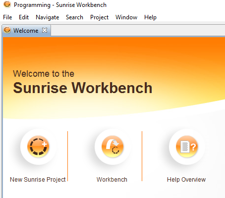
- Open KUKA Sunrise Workbench. If requested, select a suitable path for workspace or just accept the default directory. In the welcome screen, click New Sunrise Project. It is also accessible through File menu. Continue with the wizard until the project is copied to your local machine.
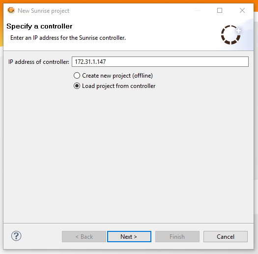
- Check if the robot is connected to the computer and that the robot IP is correct. Then mark Load the project from controller to download locally the current project from the controller. If none available, then you will need to create a new one.
Create a new project
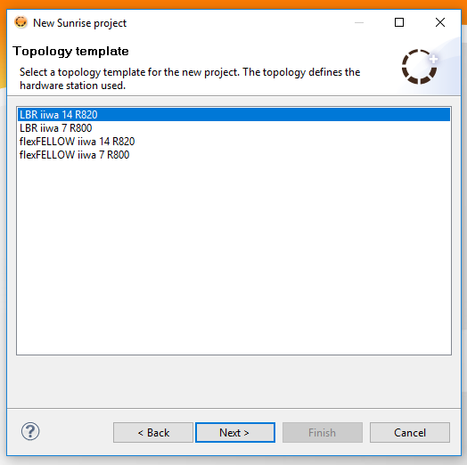
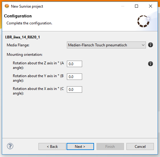
In this case, instead of selecting Load project from controller, you need to select Create new project (offline) and follow the wizard. The most important consideration by creating a new project is to select the correct robot model and gripper (media flange) you have.
Step 2: Copy file and configure
Once a project is created / imported, then you will need to: - copy DragAndBotDriver.java to your project. You may need to change the name "LBR_iiwa_14_R820_1" to yours. - copy the corresponding IO_Interface.java to your project - add tool object and port variable to the RoboticsAPI.data.xml - synchronize the project with the robot controller
Step 2.1: Copy DragAndBotDriver
You need to add the DragAndBotDriver.java file to the your project yet by drag&drop the file from Windows Explorer or by Import File functionality found on right mouse click menu. This file contains the DragAndBotDriver Java class inside the application package, which will be auto-generated if non-existing before.
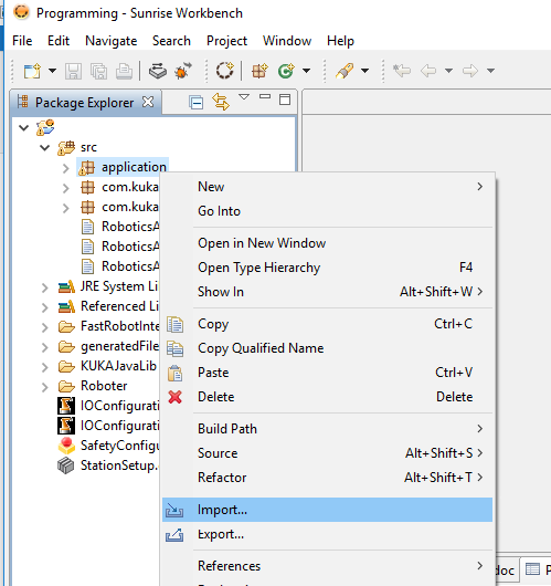
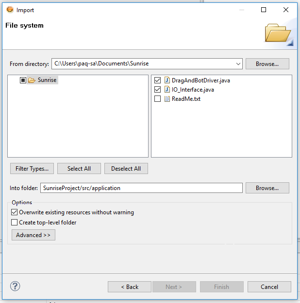
Follow the wizard to import the file: - General / File System, Next - Browse button and select the sunrise directory of the extracted zip file. - Select DragAndBotDriver.java class and click Finish.
Important
You need to load the correct robot name in the driver. As standard, if your robot model is iiwa R800, then open the DragAndBotDriver.java file and go to line no. 130 shown below (or use the search function). If you changed the robot name while creating a new project, then you need to write te corresponding correct robot name. Standard name for iiwa 14:
robot = (LBR) getRobot(controller, "LBR_iiwa_14_R820_1");
robot = (LBR) getRobot(controller, "LBR_iiwa_7_R800_1");
Step 2.2: Copy IO_Interface.java
Depending on your Media Flange you will need to copy to the project the corresponding IO_Interface.java file located in one of the following directories of the IO_Interface directory of the zip file. The same file import procedure is required as in previous step.
| Flange Type | Support Digital IO | Number of Digital Inputs | Number of Digital Outputs | Folder |
|---|---|---|---|---|
| Media Flange Electrical | No | No | No | 00_All other Media without IO |
| Media Flange Pneumatic | No | No | No | 00_All other Media without IO |
| Media Flange Inside Electrical | No | No | No | 00_All other Media without IO |
| Media Flange Inside Pneumatic | No | No | No | 00_All other Media without IO |
| Media Flange IO Electrical | Yes | 8 | 4 | 01_Media Flange IO Pneumatic & Electrical |
| Media Flange IO Pneumatic | Yes | 8 | 4 | 01_Media Flange IO Pneumatic & Electrical |
| Media Flange IO Valve Pneumatic | Yes | 8 | 8 | 04_Media Flange IO Valve Pneumatic |
| Media Flange Touch Electrical | Yes | 6 | 6 | 02_Media Flange Touch Pneumatic & Electrical |
| Media Flange Touch Pneumatic | Yes | 6 | 6 | 02_Media Flange Touch Pneumatic & Electrical |
| Light Alpha (MLA) | No | No | No | 00_All other Media without IO |
| Light Beta (MLB) | Yes | 6 | 6 | 03_Media Flange Light Beta (MLB) |
Both Media Flange Touch Electrical and Pneumatic allow impedance control mode using User button in drag&bot.
For PROFINET IOs please check the additional documentation below. You can omit this step for now.
Important
When adding additional Digital IOs into the IO_Interface.java class, please notice the following points:
- The digital input numbers must be in a sequence without any gap, starting from 1 to N inputs (ex. 1,2,3,..,10).
- The digital output numbers should be in a sequence without any gap, starting from N+1 to M output (ex. 11,12,13,..,25).
- Leaving gaps in the sequences will lead to an incorrect IO status shown at the Control Panel. Nevertheless get/set IO function blocks will still work correctly.
- The total amount of digital inputs (N) and digital outputs (M) should be the same as the variables number of digital inputs and outputs set in the component manager. (Click here to see how.)
Step 2.2: Tool configuration
Each iiwa robot needs to have a tool configured and a workpiece. The driver works using the following configuration by default: - a tool called Tool whose transformation frame is called flange_2_tool. - a workpiece called Workpiece The easy way to set them up is to replace the following objectTemplates inside the RoboticsAPIData XML tag.
<objectTemplates>
    <geometricObjectTemplate name="GeometricObjectTemplate" class=""/>
    <toolTemplate name="Tool" class="" defaultMotionFrameRef="/flange_2_tool">
        <frames>
            <frame name="flange_2_tool" id="_89b29819-b5e1-4fbc-8046-7f6f48eabe2e">
                <transformation z="0.0" y="0.0" x="0.0" c="0.0" b="0.0" a="0.0"/>
            </frame>
        </frames>
        <loadData mass="0.0" inertiaZ="0.0" inertiaY="0.0" inertiaX="0.0" cogZ="0.0" cogY="0.0" cogX="0.0" cogC="0.0" cogB="0.0" cogA="0.0"/>
    </toolTemplate>
    <workpieceTemplate name="Workpiece" class="">
        <loadData mass="0.0" inertiaZ="0.0" inertiaY="0.0" inertiaX="0.0" cogZ="0.0" cogY="0.0" cogX="0.0" cogC="0.0" cogB="0.0" cogA="0.0"/>
    </workpieceTemplate>
</objectTemplates>
Step 2.3: Driver port configuration
A new variable called port must be added in the RoboticAPIData.data.xml. This variable is defined through a processData tag which has to be placed inside processDataContainer together with other possible variable which may already exist in your project.
<processDataContainer>
    <processData id="port" value="30000" displayName="Port" defaultValue="30000" dataType="java.lang.Integer"/>
</processDataContainer>
Step 3: Synchronization
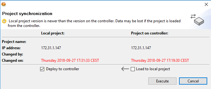
The symbol ![]() synchronizes the project with the robot controller in both directions. You can save the current project in the robot controller or retrieve the current version from the robot controller locally.
synchronizes the project with the robot controller in both directions. You can save the current project in the robot controller or retrieve the current version from the robot controller locally.
In this case you need to overwrite the project in the robot controller.
Troubleshooting / Advance information
Advance aspects of the driver installations are explained through this section.
Setup of network configuration file
This section describes how to access to the XML configuration file and how to open a network port on the robot controller.
Port check
Please check if you have access to the configuration file as follows:
- Start the KUKA controller and wait for boot.
- Connect the Windows computer with the robot controller through ethernet cable. Set the corresponding computer's network adapter address to a static IP: 172.31.1.1.
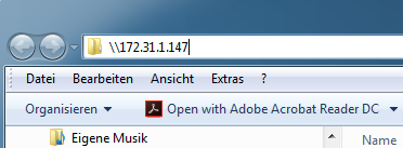
- Type the following network address in Windows (file) Explorer: \\172.31.1.147\krc\ROBOTER\Config\User\Common\KLIConfig.xml. 172.31.1.147 is the standard static IP of the KUKA controller. Depending on the user language, you may need to change ROBOTER with ROBOT. Please contact KUKA to know your user, password and domain information. The XML file will be displayed. Check if a NAT rule for port 30000 already exists in virtual5. Please check Accessing to the network configuration file for more and detailed information.
Accessing from Windows
Direction: //172.31.1.147 in Windows Explorer. Login information must be provided by KUKA.
Accessing from Linux
Type smb://172.31.1.147 in file manager. The connection will be establish through Samba protocol.
Same login data as in Accessing from Windows
Adding new NAT rule
Navigate in the Windows Explorer or Linux file browser to the KLIConfig.xml file: \\172.31.1.147\krc\ROBOTER\Config\User\Common\KLIConfig.xml. Depending on the user language, you may need to change ROBOTER with ROBOT, e.g. for english robot versions.
In virtual5 section of the KLIConfig.xml document you have to add a new rule similar to the already exiting ones:
[GlobalNatInterface] [addr] port 30000 -> [host:WINDOWS] port 30000 tcp/udp</NATRule>
Then you need to save the file and reboot the control. Probably safety activation will be required in teach pendant. If the safety password is requested and unknown please contact with KUKA.
PROFINET Configuration
If your KUKA Sunrise project already has a generated IOGroup class, you can integrate into drag&bot by modifying any of the IO_Interface.java class to call getters and setters of the IOGroup class. Assuming a ETTestIOGroup.java class is provided in the project, you need to:
- add the ETTestIOGroup object instantiation in the IO_Interface class constructor
- in get_io: call the corresponding read functions from the IOGroup
- in set_io: call the corresponding write functions from the IOGroup
package application;


import com.kuka.generated.ioAccess.ETTestIOGroup;
import com.kuka.roboticsAPI.controllerModel.Controller;
import com.kuka.roboticsAPI.motionModel.IMotionContainer;
import com.kuka.roboticsAPI.deviceModel.LBR;

/*
 * This class is configured to work with all Media Flanges which not contains any Digital IOs.
 * Media Flange Electrical
 * Media Flange Pneumatic
 * Media Flange Inside Electrical
 * Media Flange Inside Pneumatic
 * Media Flange Light Alpha (MLA)
 * Robot without any Digital IO Module
 */
public class IO_Interface {

    ETTestIOGroup ett = null;

    public IO_Interface(Controller controller)
    {
        ett = new ETTestIOGroup(controller);
    }

    /*
     * get_io : Method to get the current input/output Pin Value of the Media Flange
     * input param io_id : the input/output pin no., that it's state required.
     * output param : return the error message :"true": high , "false" : low,  "0" : done, "1" := number out of the range, "-1" = Unknown Error.
     */
    public String get_io (int io_id)
    {

        try
        {
            switch (io_id) {
            case 1: return Boolean.toString(ett.getEingang0());
            case 2: return Boolean.toString(ett.getEingang1());
            case 3: return Boolean.toString(ett.getAusgang0());
            case 4: return Boolean.toString(ett.getAusgang1());
            default: return "1";
            }
        }
        catch (RuntimeException e)
        {
            System.out.println(e);
            return "-1";        //return -1 = "Unknown Error"
        }
    }

    /*
     * set_io : Method to set the output pin Value of the Media Flange.
     * input param io_id : the output pin no. to be changed.
     * input param io_value : the output new value , to be setted.
     * output param : return the error message : "0" : done, "1" := number out of the range, "-1" = Unknown Error.
     */
    public String set_io(int io_id, boolean io_value)
    {
        try
        {
            switch (io_id) {
                case 3:
                    ett.setAusgang0(io_value);
                    return "0";
                case 4:
                    ett.setAusgang1(io_value);
                    return "0";
            default: return "1";
            }
        }
        catch (RuntimeException e)
        {
            System.out.println(e);
            return "-1";        //return -1 = "Unknown Error"
        }

    }

    /*
     * impedance_mode : Method to activate Impedance mode using User Button .
     * input param pos_axis : the selected free impedance position axis.
     * input param orint_axis : the selected free impedance orientation axis.
     * input param stiffness : the required stiffness value.
     * input param time_out : the max. time before the breaks are activated
     * input param motionContainer : the movement motion container.
     * input param robot : the robot that is controlled.
     */
    public void impedance_mode(int pos_axis, double pose_stifness,int orint_axis, double orint_stifness, double damping, int time_out,IMotionContainer motionContainer,LBR robot) {

    }
}
If the IOGroup class is not included, you will need to generate it through an additional application called KUKA WorkVisual.