Nachi CFD Controller Setup
Requirements
- The controller system version needs to be 4.72 or newer to work with drag&bot. You can see the controller system version from the main view at Service Utilities -> 13 System Version.
- No special software options are required to be installed on the robot controller.
Downloads
The required controller files can be downloaded from here: Downloads
Navigation
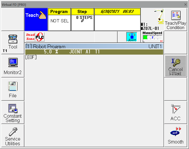
The Teach Pendant is required for the setup process and consists of two major parts, the touch screen and the button area. The most important buttons needed for the configuration are highlighted in the following pictures.
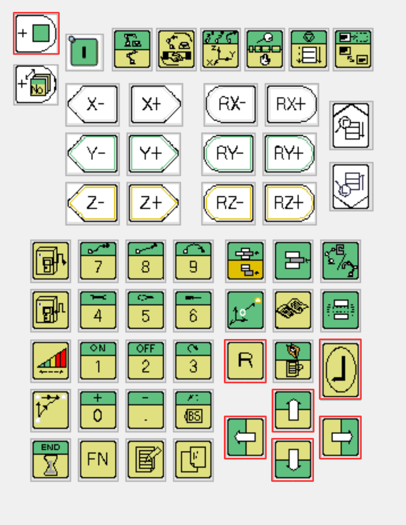
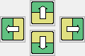
- It's possible to navigate through the different submenus using the Arrow Keys.
 .
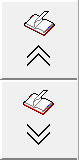
. - When a menu has several pages, two buttons appear on the right side to allow the navigation through them.
- It's necessary to confirm each change when typing numbers in text fields using the Enter button.
 .
. -
Choosing between several options is possible first by navigating to the entry field with the arrows and then change the selection by pressing one of the
 buttons while keeping the
  button pressed.
 -
After some time the teach pendant screen locks, which is indicated by a message when trying to use it. This can only be unlocked by pressing the
button.
Configure the Ethernet network
- Ensure the robot is in teach mode. The current mode is shown on the top bar.
Change to Expert Mode
- Press the
 button.
 - Select the entry R314 Change the protecting level or type 314 in the search field.
- Press the button.
- A password field opens up. Press again the button as the password for Expert is blank by default. A popup window informs you about the new mode. Press any key to continue. When you already were in Expert mode, the controller will change back to USER mode. In this case repeat the procedure.
Configure the controller IP address
- From the main view open the Constant Setting view with the soft button
 on the left side bar.
 - Change to the submenu 8 Communication -> 2 Ethernet -> 1 TCP/IP.
- Ensure the following settings are correct:
- The DHCP client is disabled.
- An IP address and subnet mask are configured and are valid for the network. Note the IP address for later. For example, a valid IP is 192.168.1.1 with 255.255.0.0 mask. Please remember that you will also need to set your Industrial PC in the same IP range to establish a communication.
- If any changes were made, then save them with the
 button in the bottom right corner. Otherwise return to the previous menu with the button.
Configure the FTP server
- From the main view open the Constant Setting view with the soft button on the left side bar.
- Change to the submenu 8 Communication -> 2 Ethernet -> 3 FTP.
- Ensure the following settings are correct:
- The FTP Service is enabled.
- Anonymous Account is allowed or only allowed.
- Connection Number is 1 or greater.
- Connection Timeout is greater zero. 900 is a good value.
- FTP Home Directory is D:¥WORK.
- Directory Permission is Read/Write.
- If any changes were made, save them with the button in the bottom right corner. Otherwise return to the previous menu with the button.
Upload the program and configuration files to the controller
Info
Uploading the program and configuration files requires the IP address and FTP server to be configured correctly.
Info
Uploading the program and configuration files can be performed with any FTP client software. In this guide the upload is shown with software available on the drag&bot IPC with Ubuntu 20.04 system. Alternatively you can use any other FTP client such as Filezilla. In this case you can install it through sudo apt-get install filezilla in the Linux terminal.
- Download and unzip the correct drag&bot Nachi controller files from here. Consider to use the correct files for the CFD or CFDS controller.
- The downloaded and unzipped directory should contain two subdirectories PROGRAM and PLC and several configuration files.
- If your robot is not the Nachi MZ07L model it's necessary to rename the file MZ07L-01-A.001 in the PROGRAM directory to match with your robot model, e.g. if you have a MZ04D robot with revision number 2, rename the file to MZ04D-02-A.001. The revision number is important to state in the filename, otherwise the controller will not recognize the file correctly. The actual robot model can be seen at Service Utilities -> 13 System Version.
- Open a new window of the standard program File Manager.
- In the text field displaying the directory path enter the path to the ftp server ftp://ip_address, where you replace ip_address with the IP address of the controller noted before. Example: ftp://192.168.0.1
- The File Manager will open the WORK directory on the robot controller. It behaves like any other regular directory on the computer.
- Copy the content from the PROGRAM directory of the downloaded and unzipped file into the PROGRAM directory of the controller. Replace already existing files.
- Copy the content from the PLC directory of the downloaded and unzipped file into the PLC directory of the controller. Replace already existing files.
- Copy the configuration files in the unzipped directory to the WORK directory of the controller. Replace already existing files.
- Close the FTP File Manager window.
- Restart the controller.
Compile the programs on the controller
- Change the controller to teach mode.
- Change the controller to expert mode.
Stop Usertasks
- From the main view open the Service Utilities view with the soft button
 on the left side bar.
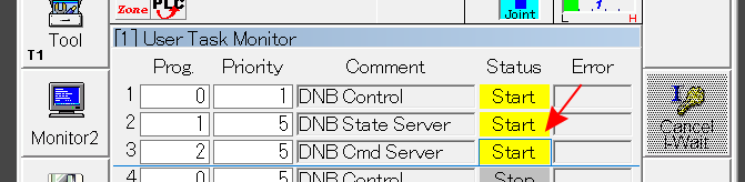
 - Change to the submenu 3 Monitor 1 -> 37 User Task -> 1 User Task Monitor.
- Ensure no usertask is running any more. Stop running usertasks by selecting the respective status cell (a thin blue border has to be around the status field) and press together with
 .
.
Compile Programs
- From the main view open the Service Utilities view with the soft button on the left side bar.
- Change to the submenu 9 Program Conversion -> 8 Language.
- Ensure that Source→exe is selected under Conversion Type.
- For the files MZ07L-01-A.001 (or renamed respectively), USERTASK-A.000, USERTASK-A.001, USERTASK-A.002 and USRPROC.INC perform the following steps:
- Place the cursor on the respecive file with the touch screen and the
 buttons and select it with the button. Compile the selected program with the
  soft button on the bottom right.
 - Eventually confirm to overwrite an already existing file.
- Another dialog opens and informs whether the compilation has succeeded or not. In case of success "Normal end" should be stated at the end. Press the button to close the dialog.
- Deselect the file with the
 button.
 - Repeat the steps for all files.
Adjust the PLC Program for using with KeTop
In case the Nachi Robot is used in combination with a KEBA KeTop, the PLC program needs a small addition that the speed is only limited to 250mm/s in KeTop teach mode. Follow these steps to adjust the PLC program correctly.
- Change the controller to teach mode.
-
Change the controller to expert mode.
-
From the main view open the Service Utilities view with the soft button
on the left side bar. - Change to the submenu 14 PLC Program Edit -> 1 PLC Program Edit.
- Select the latest version of the PLC program and confirm with the soft button on the bottom right.
- The PLC program editor will open.
- Scroll down to the bottom after the last rung with the arrows.
- Add a new rung with the
 soft button while pressing the button.
 - Select the first contact in the new rung:
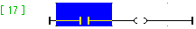
- Change the contact to be a B-Contact with the
 button:
- Edit the contact source be clicking when the contact is selected. The button menu on the bottom changes.
- The contact, which shall be used and needs to be entered now, depends on your setup:
- If the Nachi Robot Monitoring Unit (RMU) is part of your setup, configure the output O194. Click the
 soft button while pressing the button. Afterwards type 194 with the keypad buttons. When confirming with , the rung changes to
- Otherwise the physical input, where the KeTop signal for manual mode is wired to, has to be configured. This depends on the digital I/O board and the pin it is wired there.
- Click the
 soft button while pressing the button. Afterwards type the input number depending on the setup as described below. When confirming with , the rung changes for example to
 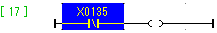 for the Mini I/O Board Input 8 connection.
- Digital I/O Board 1: Input 1 -> X0, ..., Input 32 -> X31
- Digital I/O Board 2: Input 1 -> X65, ..., Input 32 -> X95
- Digital I/O Board 3: Can not be used to connect the KeTop Wiring to the Nachi Controller.
- Mini I/O Board 1: Input 1 -> X128, ..., Input 8 -> X135
- If the Nachi Robot Monitoring Unit (RMU) is part of your setup, configure the output O194. Click the
- Select the second contact in the rung:
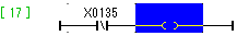
- Edit the contact source be clicking when the contact is selected. The button menu on the bottom changes.
- Configure the input I147. Click the
 soft button while pressing the button. Afterwards type 147 with the keypad buttons. When confirming with , the rung changes e.g. to
 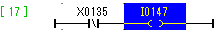 .
. - Change the button menu with the
 soft button.
 - Save the PLC program with the
 soft button while pressing the button.
 - Save the current PLC program by pressing the button in the bottom right corner.
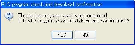
- Confirm to check the updated PLC program and to use it with Yes in the following dialog:
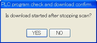
- Press the soft button to perform this and confirm it again with Yes:
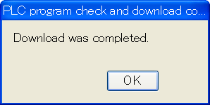
- Confirm the download was completed:
Restart the controller.
Activate the PLC program on the controller
This step can be skipped, if the PLC Program was adjusted as described one step before.
- Change the controller to teach mode.
- Change the controller to expert mode.
- From the main view open the Service Utilities view with the soft button on the left side bar.
- Change to the submenu 14 PLC Program Edit -> 2 PLC Program Verify.
- Select the latest DNB_PLC.stf program and press Execute. A message indicating that the program is the same must appear. Otherwise follow the next steps.
- Go one submenu back and change to the submenu 3 PLC Program Check and Download.
- Select the latest DNB_PLC.stf program and press Execute.
- A message "Compile was completed. Is download started after stopping scan" has to appear.
- Choose "Yes". After the download has been completed confirm this with "Ok".
Configure Advanced Settings
- Configure more advanced settings, like tool weight as described here. The tool weight has significant impact on the maximum speed the robot can reach during movements.
Setup for drag&bot Studio
- Please select Nachi CFD Controller from the dropdown menu in the drag&bot Component Manger.
- Configure the parameter IP for your setup. It has to match with the IP found in the section Configure the ethernet network.
- Configure your Robot Model for visualization. If your model is not listed, you can use the "-" entry to work without visualized robot model.
- Configure which digital I/O boards are set up in your controller. The I/Os use the same mapping as the hardware I/O boards, not the mapping of the CFD controller. The digital I/Os, which can be used, depend on the existing hardware and its settings.