General
The CODESYS works as a Modbus TCP/IP slave. The steps below show how to add the Modbus TCP/IP slave device in the CODESYS and how to configure it.
Important
- Programs names should contains alphabet characters, using numbers only is not allowed.
- The following steps show the PLC program which accepting a program name with maximum of 20 characters. If you need to use longer programs names, please adapt the PLC program to holds and deals with more registers.
- To write variable values onto the modbus holding register it is necessary to add a Modbus TCP/IP Master > Slave module in CoDeSys
Requirements
Below codesys packages are required for the Modbus TCP/IP communication.
- CODESYS Modbus TCP Device SL.
- CODESYS Modbus TCP Master SL.
Setup
Set Global Variables
-
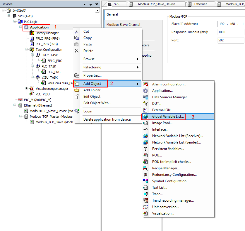
Right click on the Application and select Add Object then Global Variable List...
-
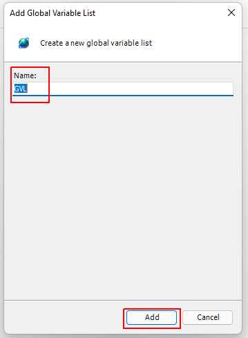
Keep the GVL name, and click Add.
-
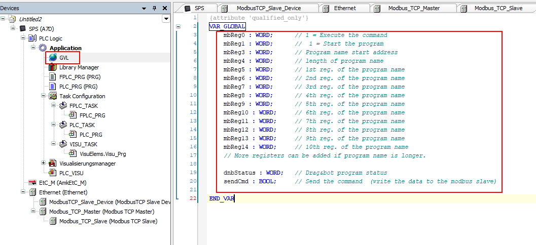
Add global variables as shown below.
Add Ethernet Interface
-
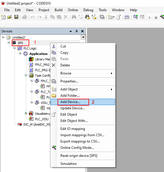
Right click on your PLC and select Add Device.
-
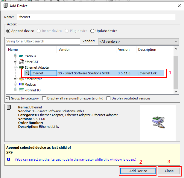
Under the Ethernet Adapter add the Ethernet interface. (if not added in your PLC).
-
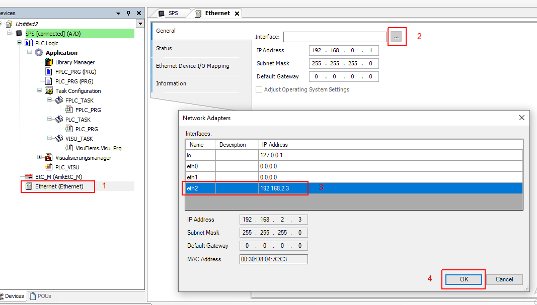
Double click on the Ethernet interface, then under the Interface select the adaptor interface to be used.
Add Modbus Slave/Server
-
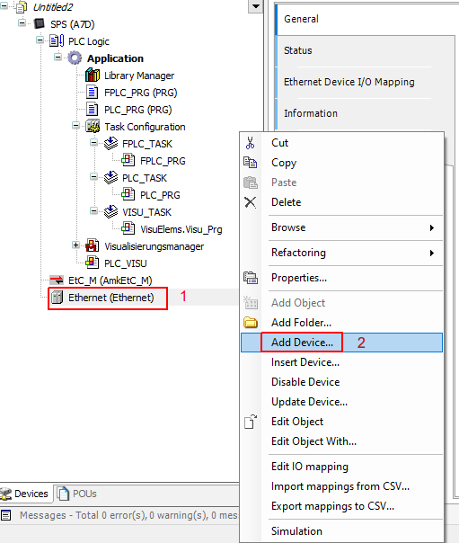
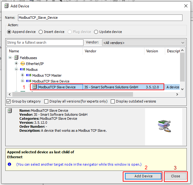
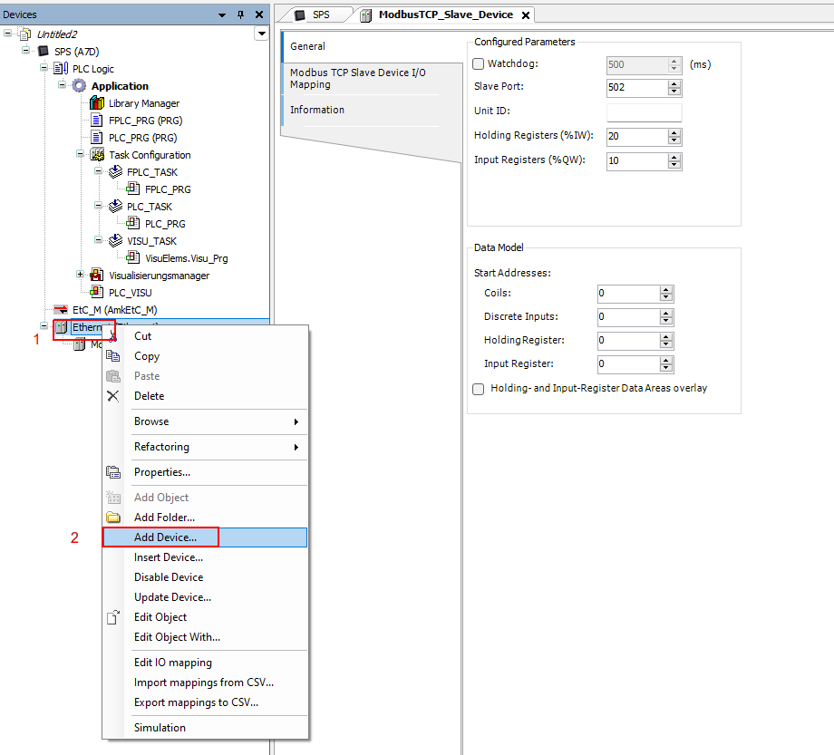
Right click on the Ethernet interface, and click on Add Device.
-
Select the Modbus then ModbusTCP Slave Device and add the ModbusTCP Slave Device.
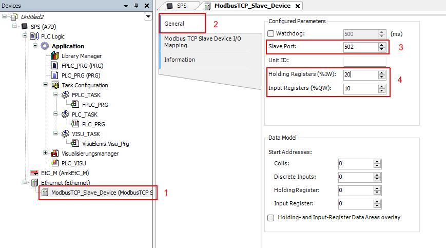
-
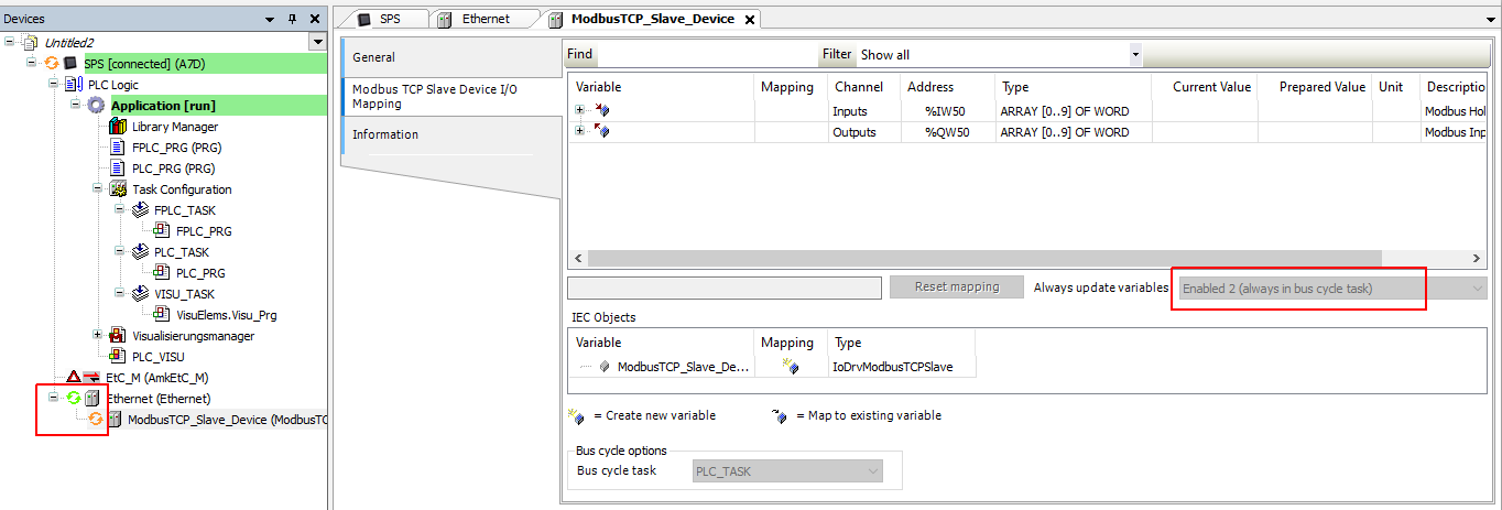
Double click on the ModbusTCP Slave Device, then select the required communication port and the number of the Holding & Input Registers (Min. 15 Holding Registers are required, these 15 registers is reserved for the drag&bot control header and should not be used by the user for application purposes).
-
From the Modbus TCP Slave Device I/O Mapping select the bus cycle task that the Modbus should with and link register number 2 to your global variables. Register number 2 (
Inputs[2]) contains the drag&bot program status.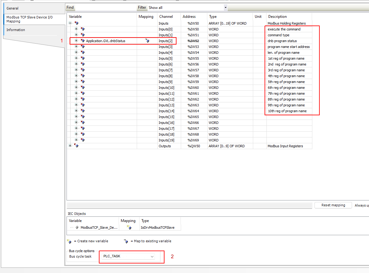
Add Modbus Master/Client
Codesys does not allow to write to the slave holding registers directly. We cannot just map a CoDeSys variable in this case. We need to add a Modbus Master and use it to write these registers.
-
Right click on the Ethernet interface, and click on Add Device.
-
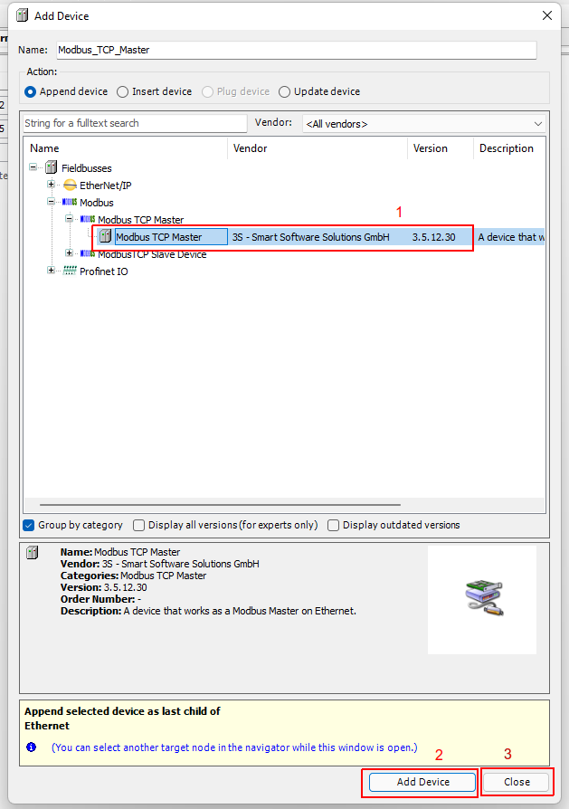
Select the Modbus then ModbusTCP Master and add the ModbusTCP Master.
-
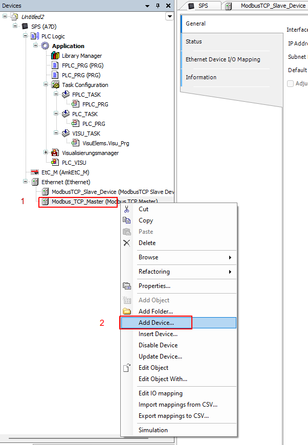
Right click on the Modbus TCP Master interface, and click on Add Device.
-
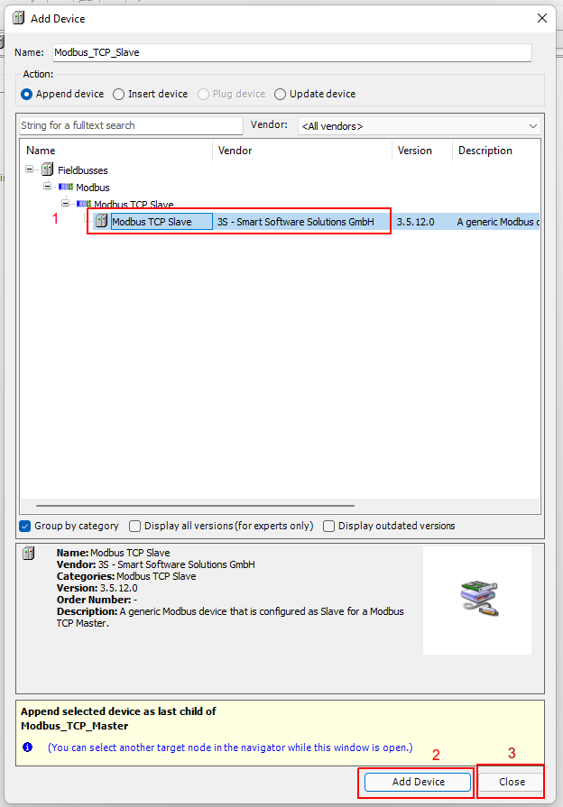
Select the Modbus then ModbusTCP Slave and add the ModbusTCP Slave.
-
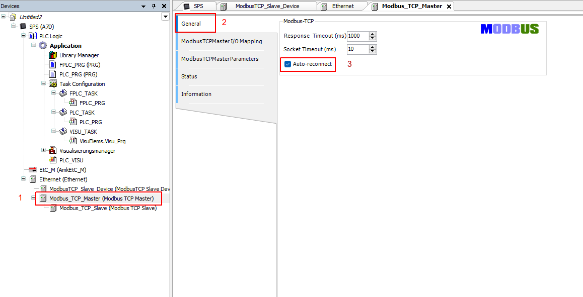
Double click on the Modbus TCP Master and under the General tab, activate the Auto-reconnect.
-
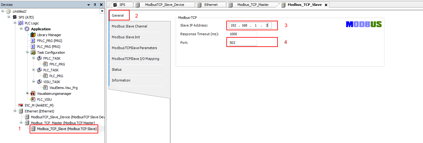
Double click on the Modbus TCP Slave and under the General tab, enter your PLC IP number and modbus slave port number.
-
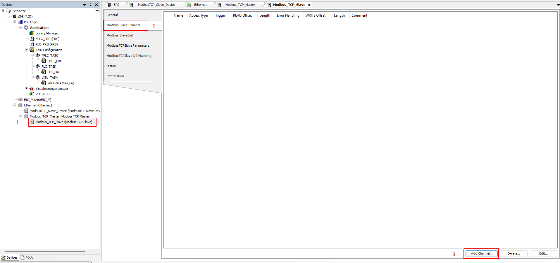
Under the Modbus Slave Channel tab, select Add Channel.
-
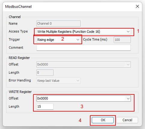
Under access type select Write Multiple Registers (Function Code 16). Under Trigger select Rising edge, and under Length put 15, then click OK.
-
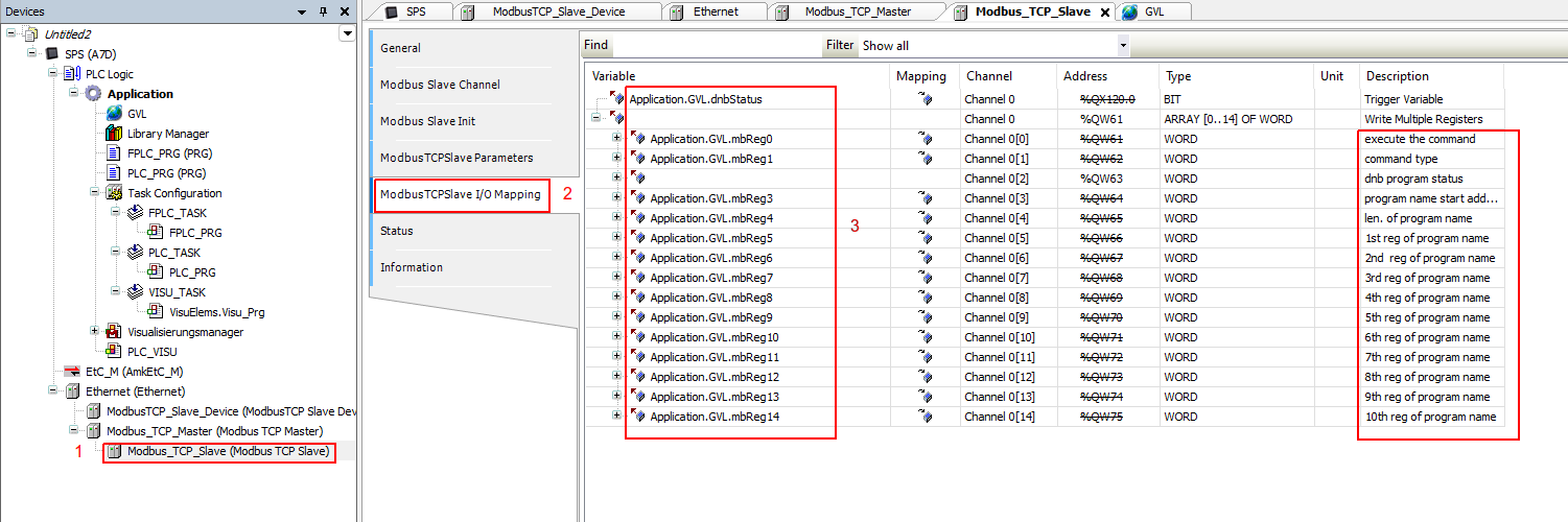
Under the ModbusTCPSlave I/O Mapping , link the registers to your global variables as shown below.
Change the Program Name to words array
In order to convert the program name from a string type into a word type (used by the modbus registers), you need to add and use the below function block. This function block is deigned to process a program name with maximum of 20 charterers. You can modify it to process longer program name if required.
-
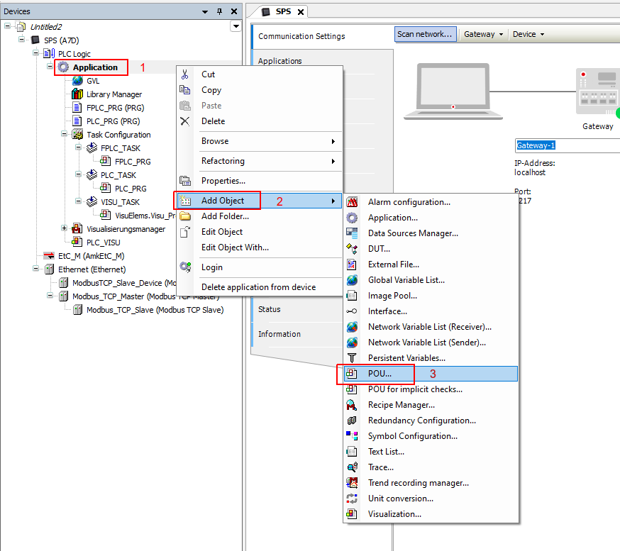
Right click on the Application and select Add Object then POU...
-
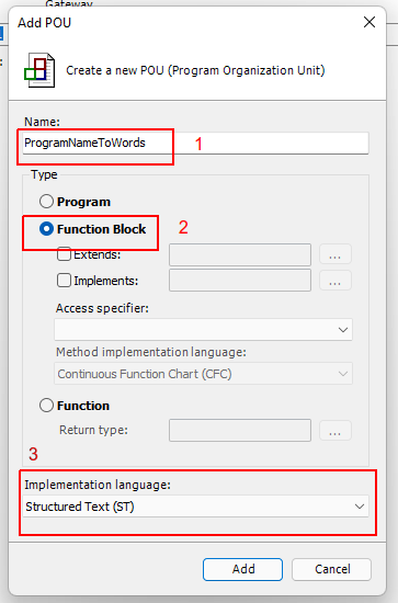
Enter the function block name , select type as a Function Block and choose Structured Text ST as an implementation language.
-
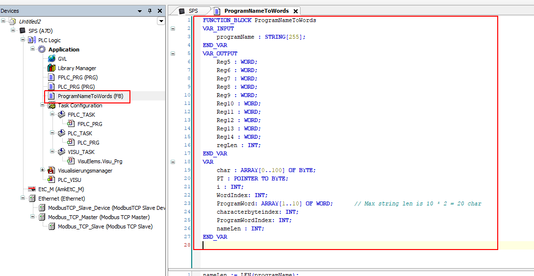
Add the function block variables as shown below. Code is DOWNLOAD

-
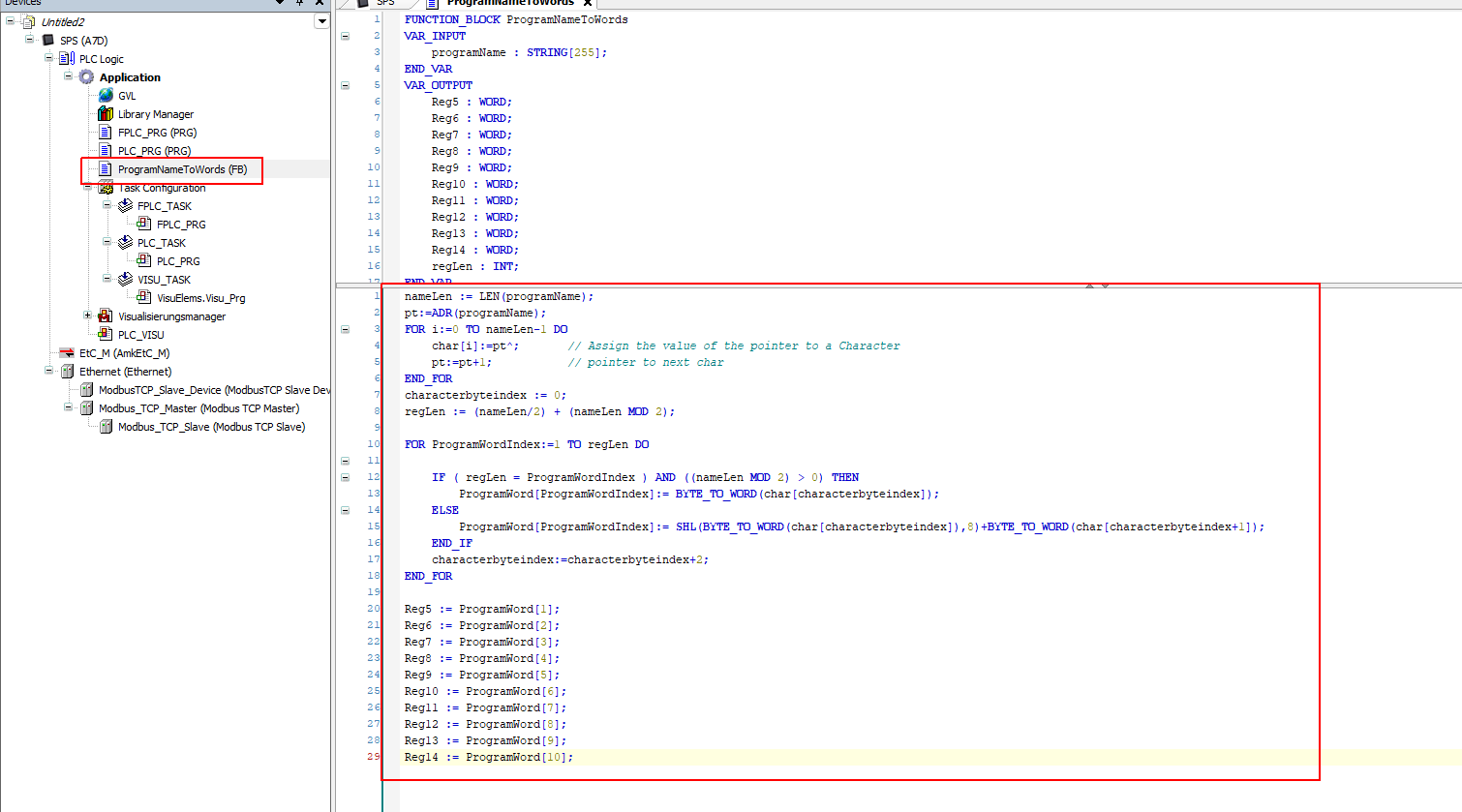
Add function block body as shown below. Code is DOWNLOAD
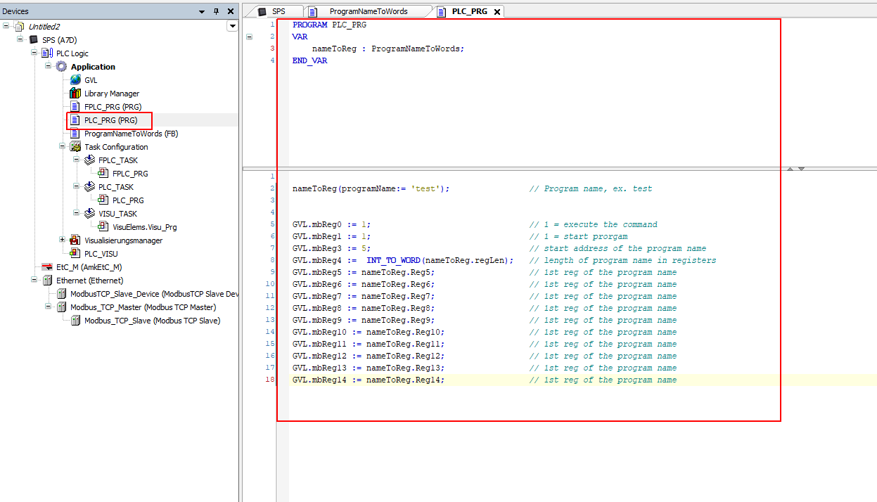
PLC Task Program
-
In the PLC Task program, add below code and variables. Code is DOWNLOAD
-
You can link the enabling bit (sendCMD) of the modbus master channel writing functionality to an HMI push button to activate the modbus writing (program triggering).
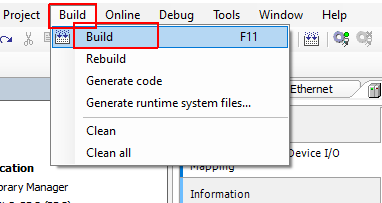
Build
-
From the Build menu select Build.
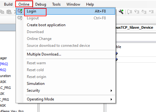
-
From the Online menu select Login to download the project to the PLC.
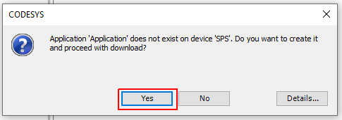
-
Click on Yes.
-
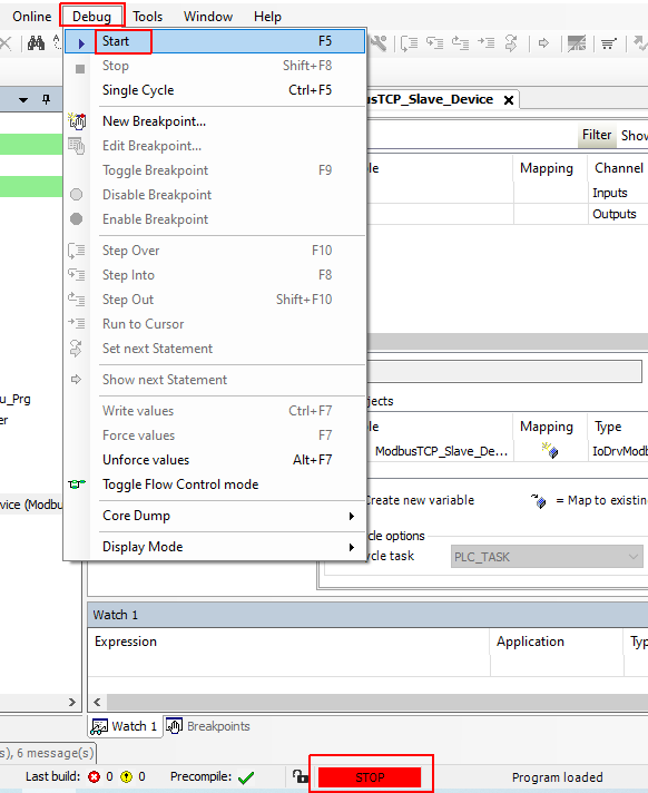
From the Debug menu click Start, The PLC status in the bottom should be Running and green.
-
The symbol beside the Modbus slave should be Orange (ready for communication), now start the Dragandbot and add the Modbus Module (Enter the PLC IP number and port number. Activate
Use Headeroption in the module configuration). For debugging, you can activate the Always update variables to see the real time registers values.