EPSON Digital IO Wiring
Warning
- Please refer to the official documentation for the exact pin numbers and wiring diagrams, they may differ betweend controller versions.
- Please read carefully the "Standard I/O Connector" chapter of your controller manual before start working with the IO wiring.
Important
- The information in this page is based on the EPSON "SCARA ROBOT T SERIES MANIPULATOR MANUAL, Rev. 10, manual no. EM198R4080F".
- Use the information below under your responsibility. The drag and bot GmbH assumes no responsibility or liability for any possible damage or injury resulted from it.
Important
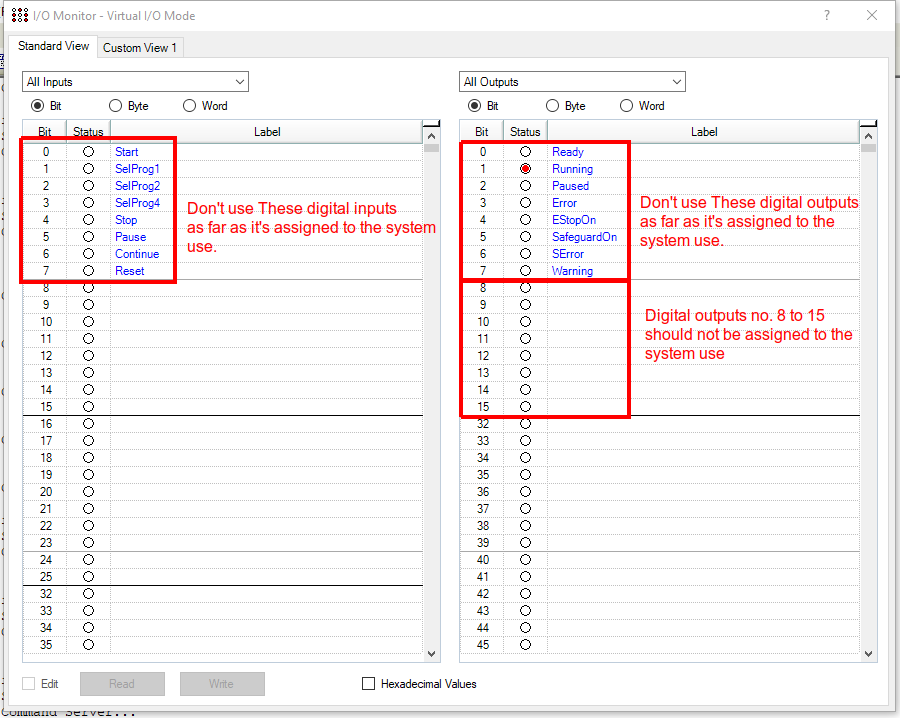
- By default, Epson assign/use the digital inputs no. 0 to 7 and the digital outputs no. 0 to 7 for the system use. You should not use these digital inputs/outputs as far as it's assigned to the system use.
- The Controller Digital Outputs pins 8 to 15 should not be assigned to any of the system status output signal, otherwise setting the controller digital IOs will not work.
- You can change the system status output signals and their assignment at: Setup Menu -> System Configuration -> Controller -> Remote Control -> Outputs.
Requirements
- External power supply with 12 VDC or 24 VDC based on your digital IOs device requirements.
Digital Inputs
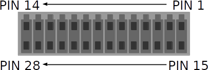
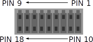
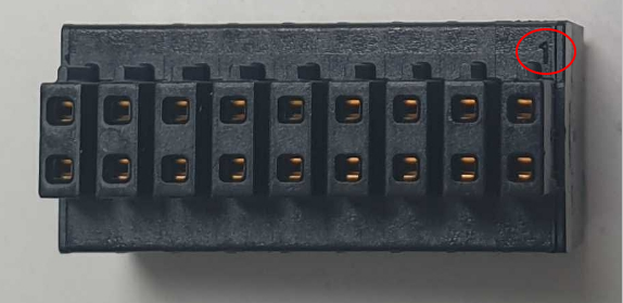
Digital Inputs Connector
The digital inputs of the EPSON T series robot required connector type Phoenix Contact DFMC 0,5/14-ST-2,54 at the cable side.
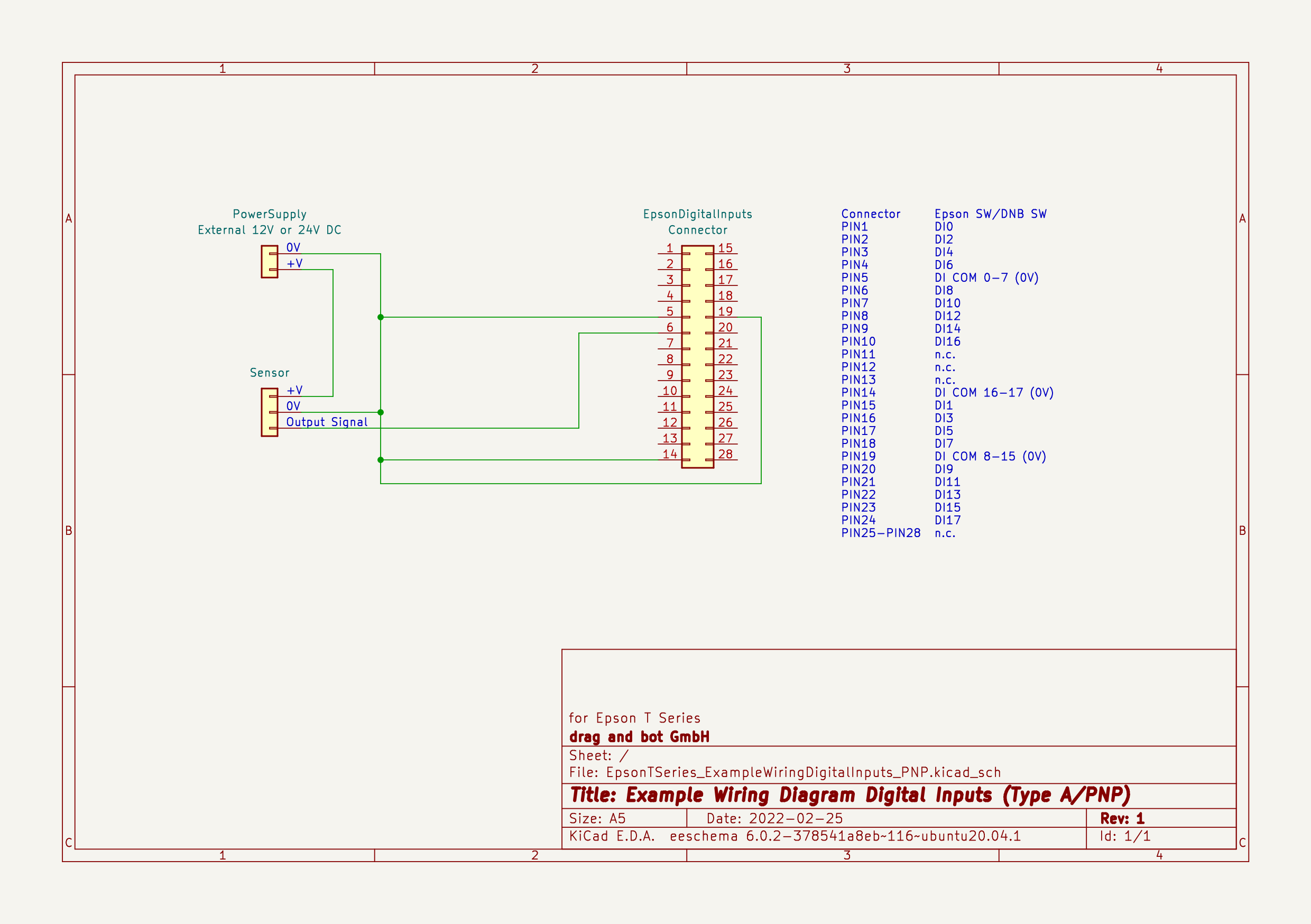
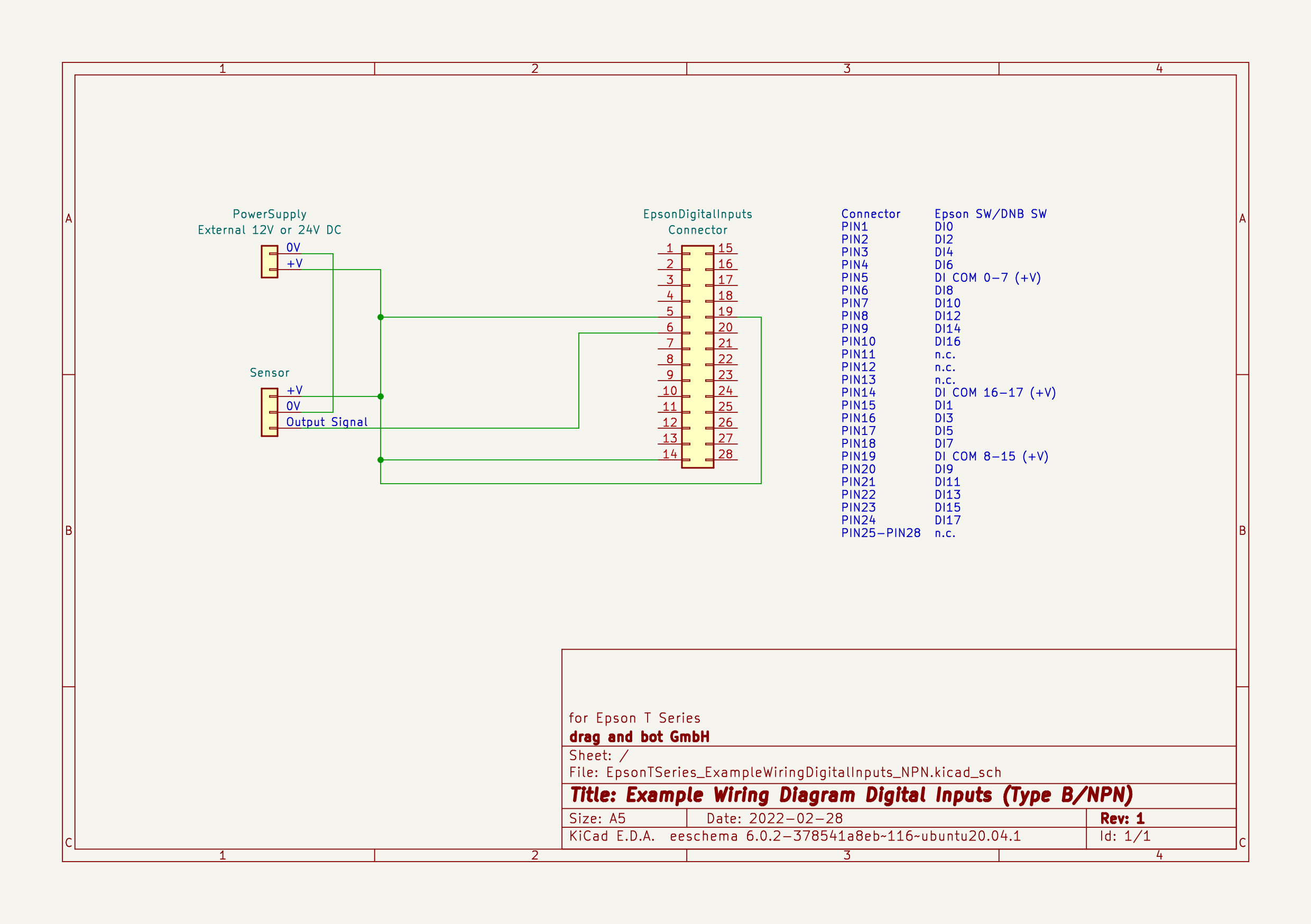
Digital Inputs Wiring Diagram
Based on the connected sensor type, there are two wiring diagrams:
Warning
- The wiring diagram below is based on the Epson T series robot manual. Other Epson robot models might have a different IOs pin assignment, please always check your robot manual for the exact pin assignment.
Type A (PNP)
Type B (NPN)
Digital Outputs
Warning
- Be careful with the digital outputs wiring as it has no protection against short-circuit and reverse-connection. Wrong wiring may cause damage to your controller.
Below are the main specification for the EPSON T series digital IOs, please refer to your robot manual for more details.
- Rated Output Voltage : +12 V to +24 V ±10%
- Maximum Output Current : TYP 100 mA/1 output
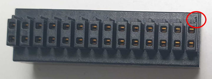
Digital Outputs Connector
The digital outputs of the EPSON T series robots required connector type Phoenix Contact DFMC 0,5/9-ST-2,54 at the cable side.
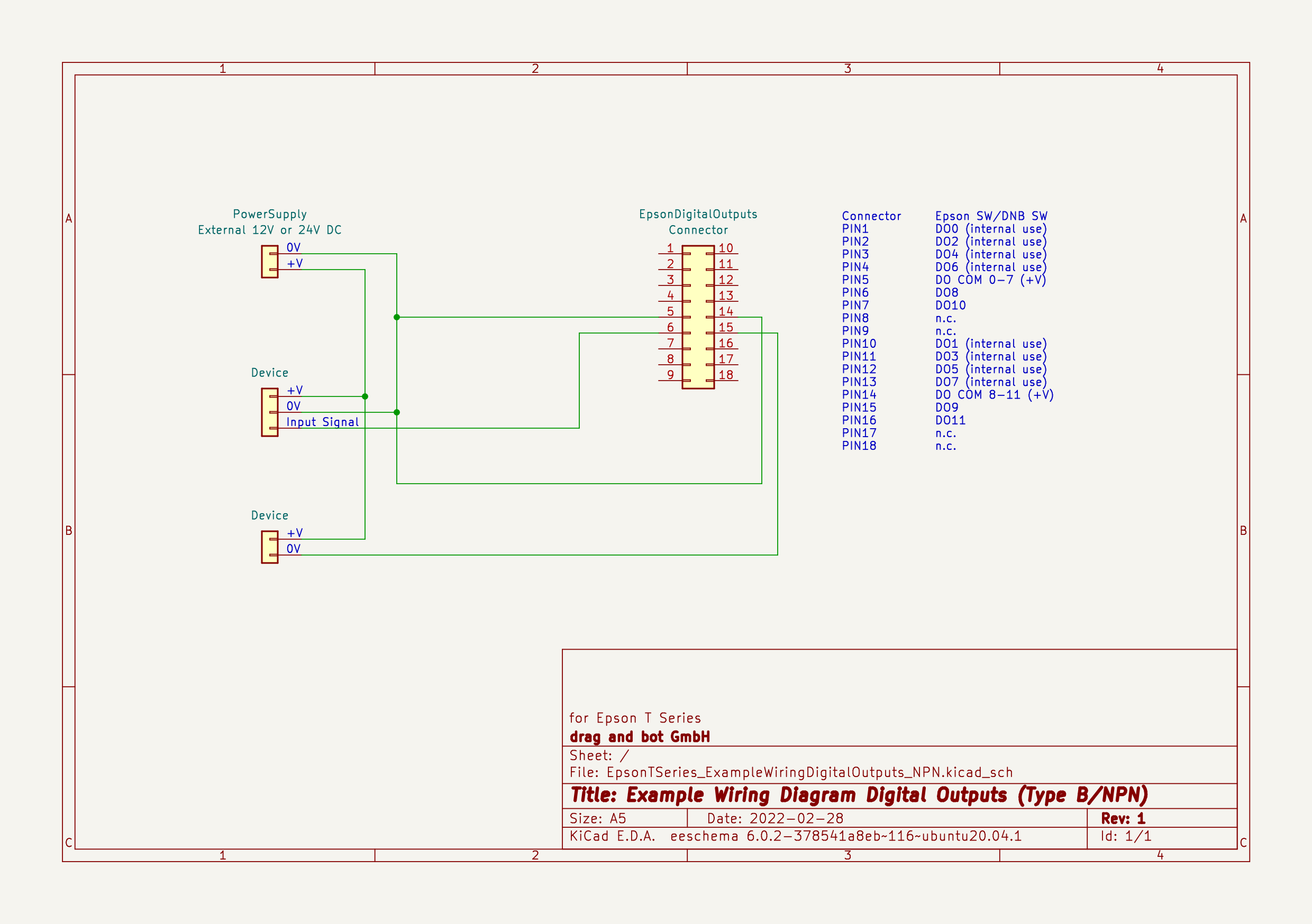
Digital Outputs Wiring Diagram
Based on the connected device type, there are two wiring diagrams:
Warning
- The wiring diagram below is based on the Epson T series robot manual. Other Epson robot models might have a different IOs pin assignment, please always check your robot manual for the exact pin assignment.
Type A (PNP)

Type B (NPN)