Define multiple small grids in a big grid structure (= meta grid)
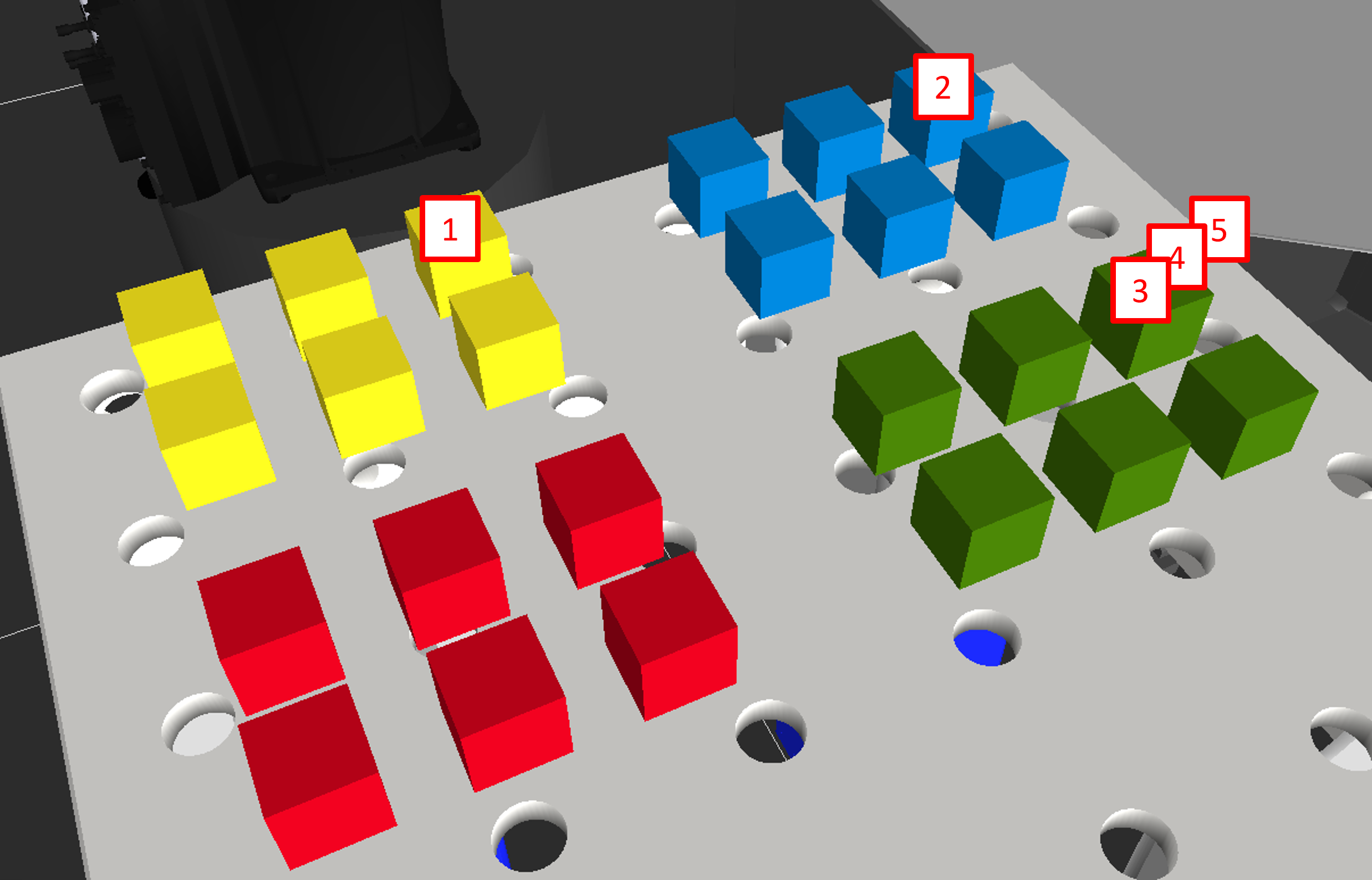
In case your application contains a setup where multiple small grids are placed in a big grid structure as in the pictures below and you do not want to define each small grid individually, here is an approach to duplicate the small grids based on a big grid structure. This big grid structure is called here "meta grid", the small grids are called "subgrids".
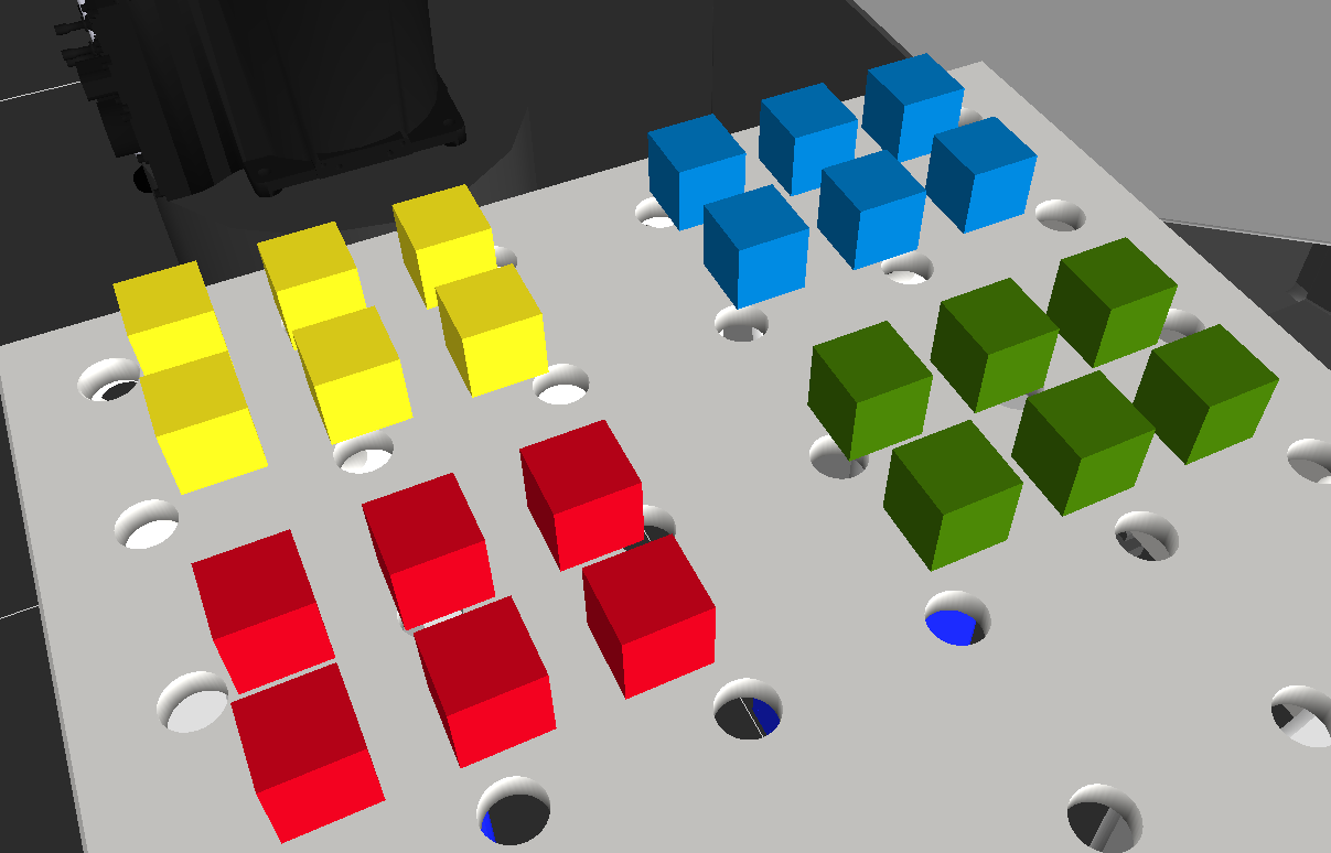
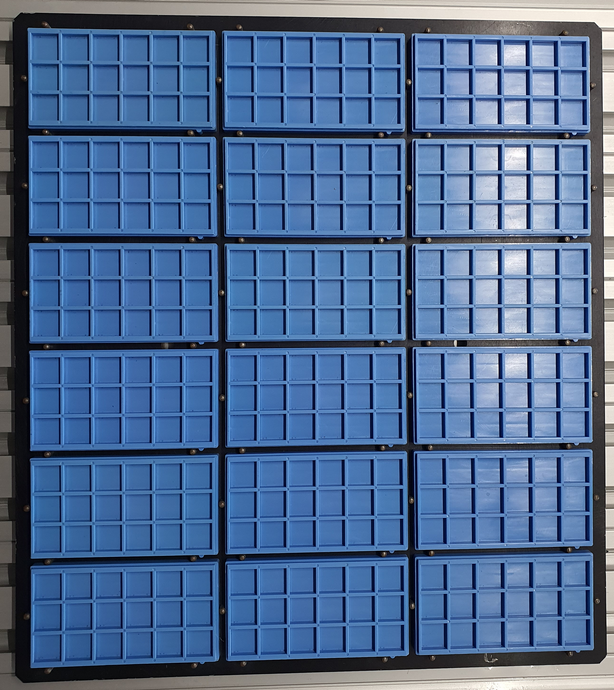
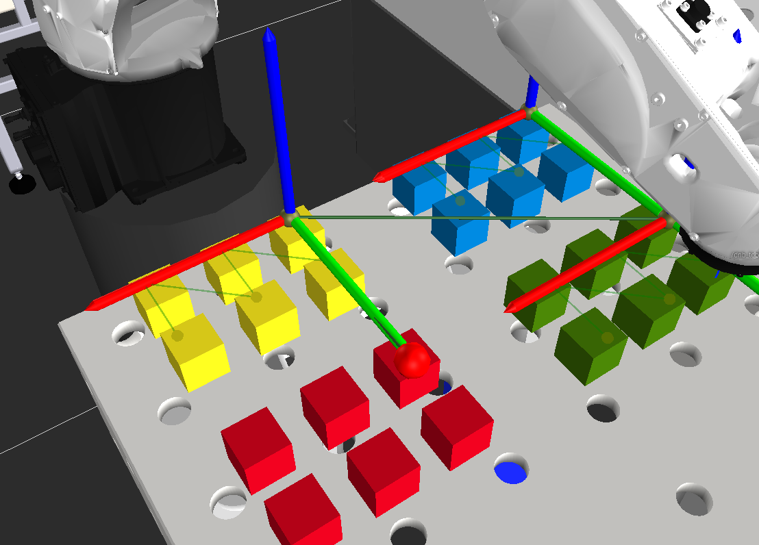
Your setup might look similar to one of these:
Prerequisite
The prerequisite for using this approach is that all subgrids have the exact same dimensions and are equally spaced next to each other. Further you should be familiar with defining and teaching grids in drag&bot.
Program template to setup the metagrid and the subgrids
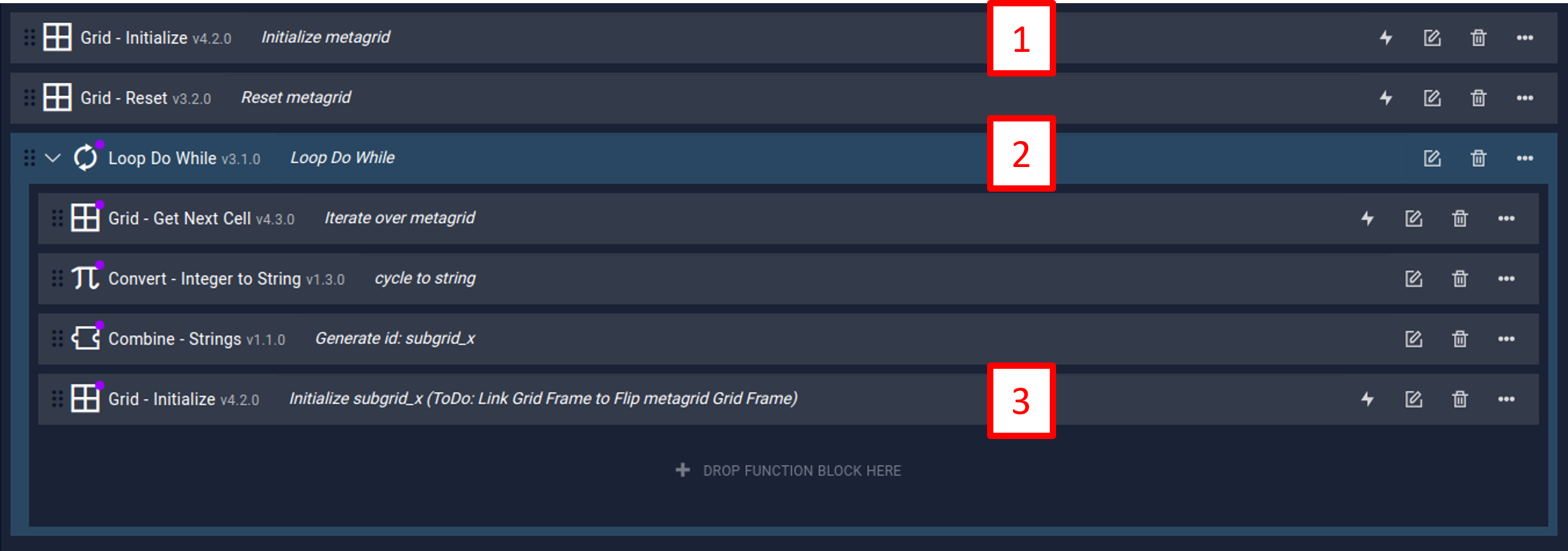
This program can be used as template to set up the meta grid and subgrids:
How it works
In (1) the meta grid is defined that consists of one cell for each subgrid. The loop (2) iterates over each cell of the meta grid and in (3) defines a subgrid at each cell position of the meta grid.
How to adapt the template to your application
To adapt the template to your grid arrangement do the following steps:
-
The meta grid is treated like a normal grid, where each subgrid is one cell. Adapt the meta grid to your subgrid arrangement by clicking on the "Set parameters" icon of Initialize metagrid. The Palletizing Wizard will be shown. Modify the data in step 1 (Choose grid type), step 2 (Set grid), step 3 (set corners) and step 4 (Grid position) of the Palletizing Wizard. In step 4, the "Grid approach position" (4) and the "Grid position" (5) must be identical to the Right cell corner (3) position from step 3.
-
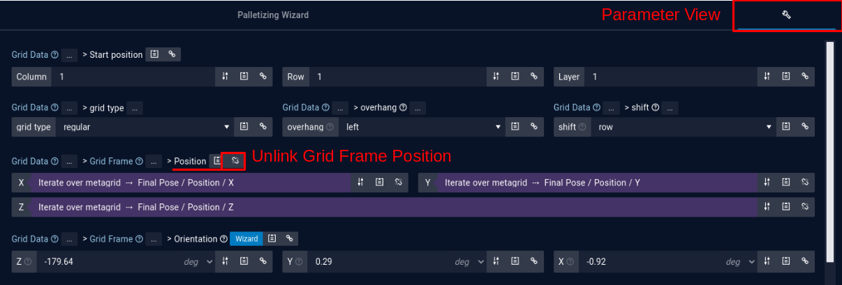
Open the Initialize subgrid_x function block by clicking on the "Set parameters" icon. Change to the Parameter View and unlink the Grid Frame Position parameter. Unlinking is necessary here as otherwise the grid can not be teached in the next step.
-
Adapt the subgrid to your subgrid structure by clicking on the "Set parameters" icon of Initialize subgrid_x. Modify the data in step 1 (Choose grid type), step 2 (Set grid), step 3 (set corners), step 4 (Grid position) and step 5 (Choose pattern). Do not modify the grid ID in step 6 as it is linked to allow for the creation of multiple grids according to the meta grid.
-
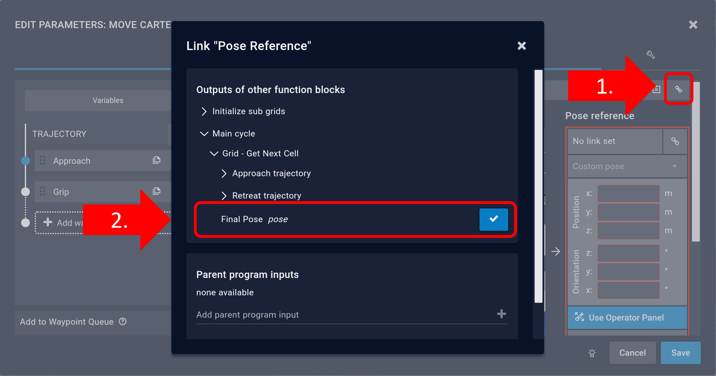
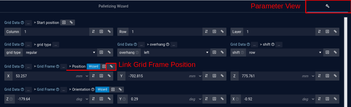
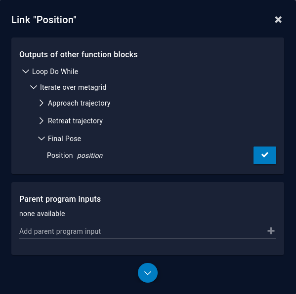
Link the Grid Frame Position in the Parameter View to the Final Pose Position of the Iterate over metagrid function block.
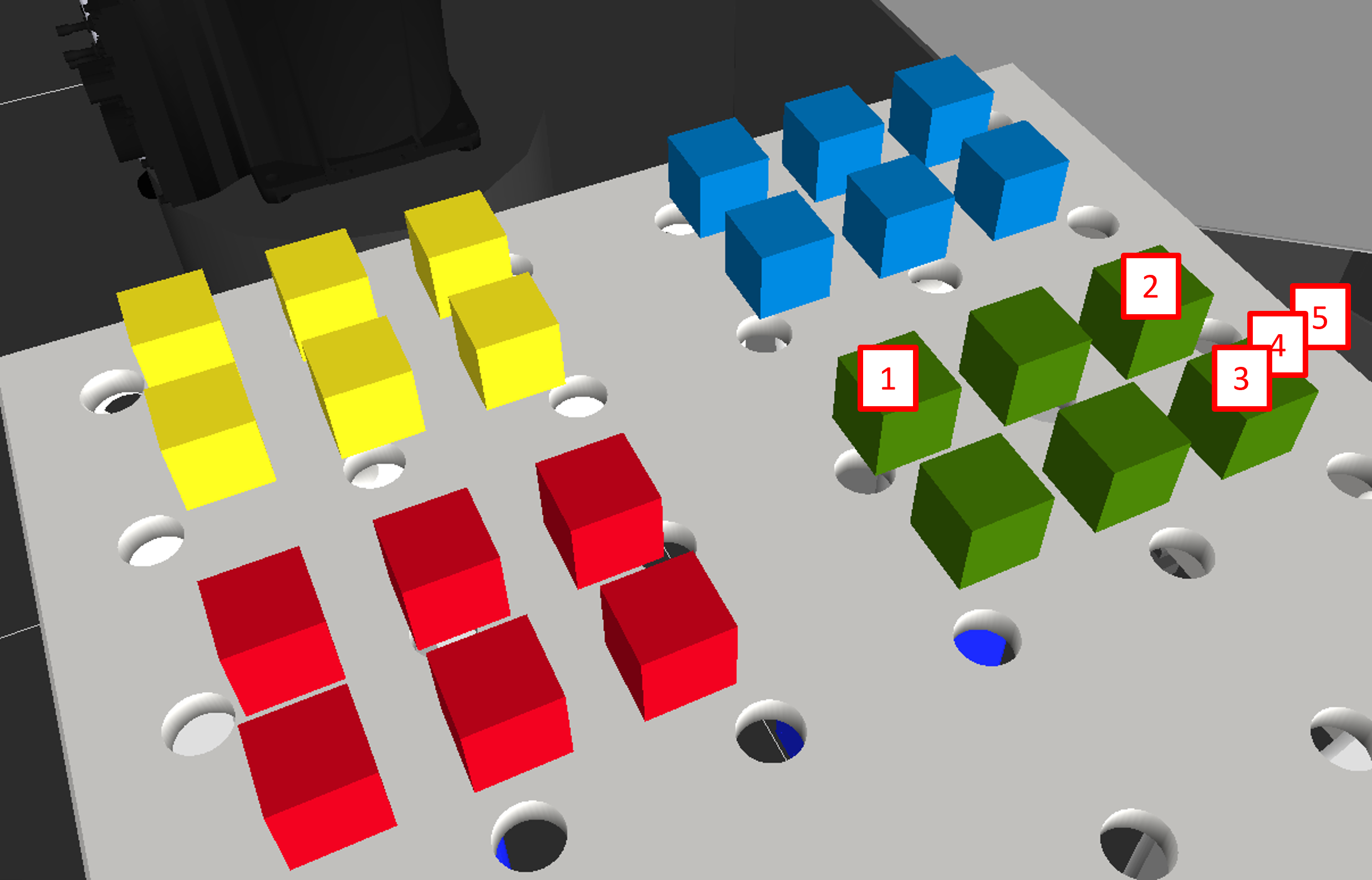
When the program is executed the metagrid and subgrids will be created. Note that normally the grids are not shown in the 3D visualization on initialization so you might not see the subgrid structure as in the following picture.
How to use the meta grid
Example Application - Meta Grid 
Example Application - Meta Grid - Scenario
The picture below shows the structure of the provided example application that makes use of the meta grid. It has 3 parts.
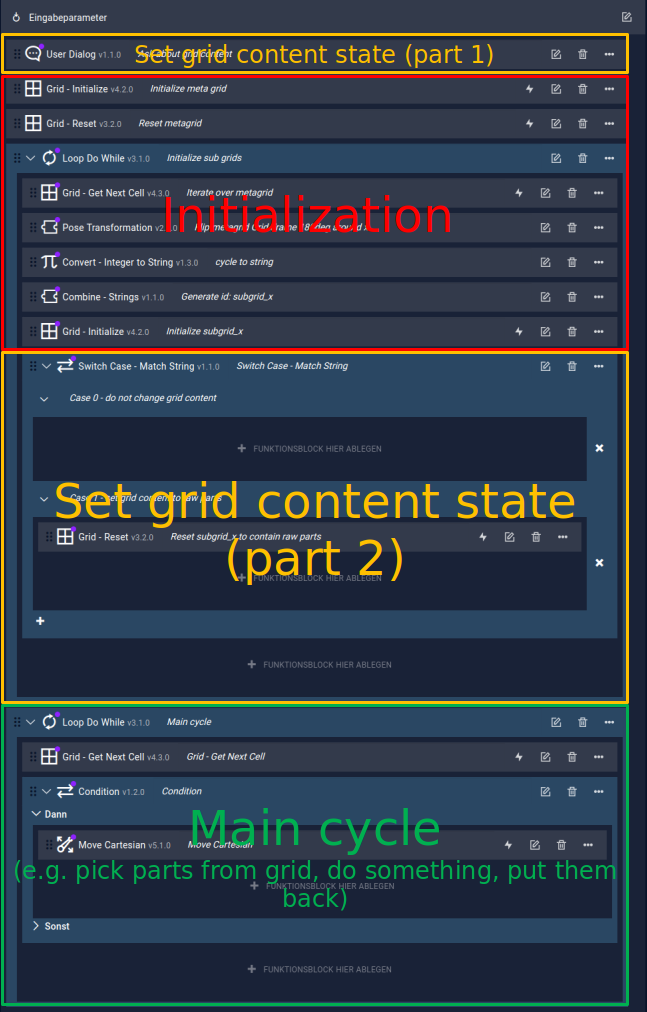
Part 1: Initialization
The meta grid initialization is described in detail in the previous chapter. The initialization must be placed at the beginning of each program that uses meta grids to ensure that the subgrids are initialized correctly.
Part 2: Set grid content state
This part of the program ensures that all cells of all subgrids are in the desired state, e.g. if the magazines have been refilled all cells should be in the state Raw Part. Alternatively, if the program has been interrupted for some reason the cell state should not change at all. To achieve this, there is a user dialog at the beginning of the program (Set grid content state part 1) that asks the user if all cells should be set to Raw Part or if the cell state should not be changed. In this case all cells remain in the state they currently are. A Switch Case function block in the initialization loop (Set grid content state part 2) evaluates the user input to either set all cells of each subgrid to Raw Part or do not modify them.
Remark: More functionality can be added
The user dialog as well as the Switch Case function block can be enhanced to offer more options, e.g. set all cells to Empty, ...
Remark: Use Grid Manager panel
It is always possible to monitor and modify the state of each grid in the Grid Manager panel in the Operator Cockpit.
Part 3: Pick/Place parts from/in the grids
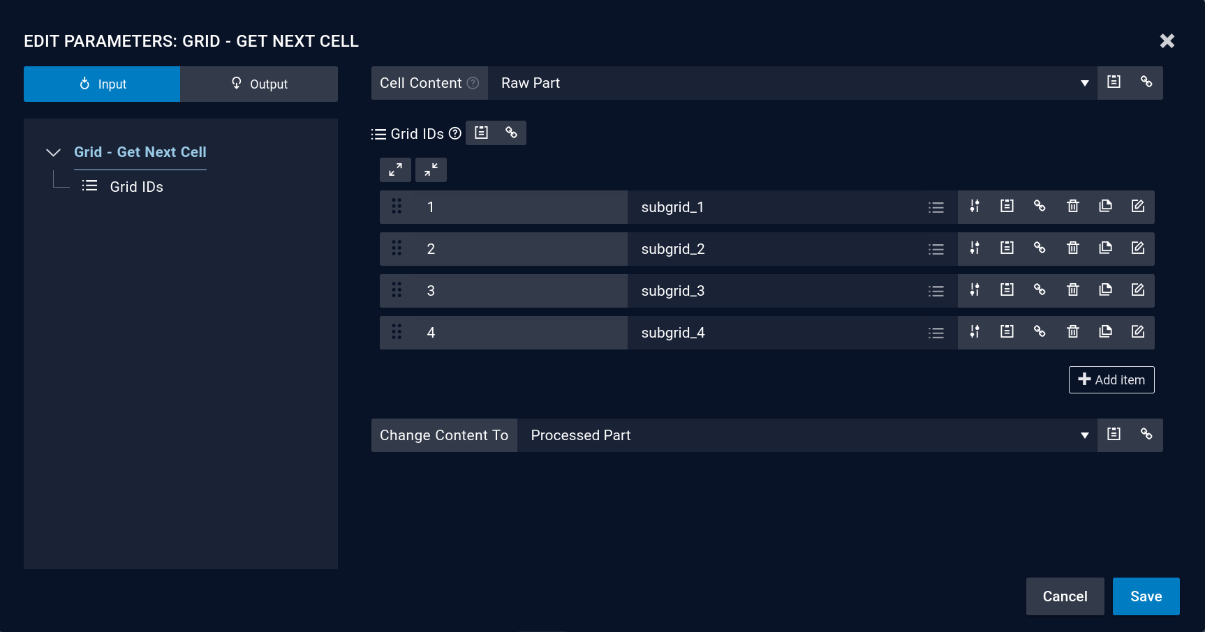
This is the main part of the program where the grids are used inside a loop. In every cycle of the loop, a grid cell is determined that will be used with the Grid - Get Next Cell function block. In the parametrization dialog of this function block you have to specify
- what kind of cell (= a cell with which state) should be searched for, in our example Raw Part.
- which grids should be included in the search and in what order they should be searched
- to what state the status of the returned cell should be switched to, in our example Processed Part.
The picture below shows how the Grid - Get Next Cell function block of the provided example application is parametrized.
To make sure that the robot only moves if a respective cell has been found, the Move Cartesian function block is placed inside a condition which is linked to the output Found Cell of Grid – Get Next Cell. The waypoints inside the Move Cartesian function block are linked to its Final Pose output as shown in the following picture.