iiwa Driver Usage
Requirements
The driver must be installed on the robot controller following the instructions.
After the driver is installed in the robot controller, a new DragAndBotDriver application will appear on the teach pendant. To use the robot with drag&bot you will need to:
- Step 1: Start the driver application
- Step 2: Configure static IP on the drag&bot IPC in range of robot controller (e.g. 172.31.1.1) and connect the IPC to it through ethernet.
- Step 3: Add the corresponding KUKA LBR iiwa drag&bot component in the Robot System. Configure robot IP and the number of available IOs corresponding to the flange set.
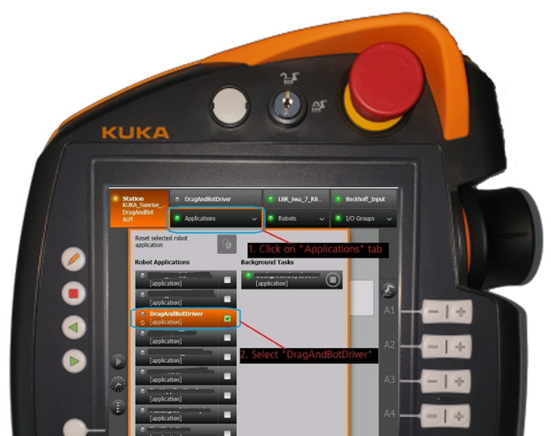
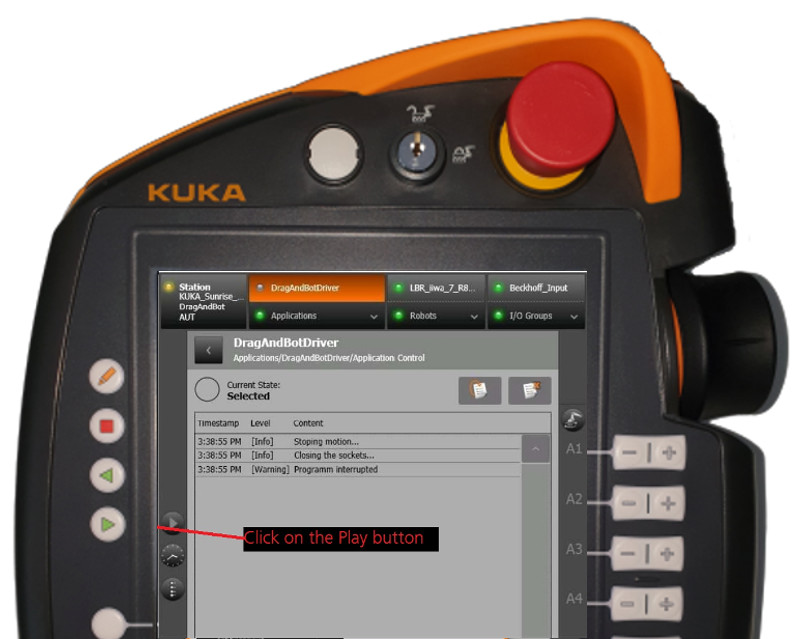
Step 1: Start the driver application
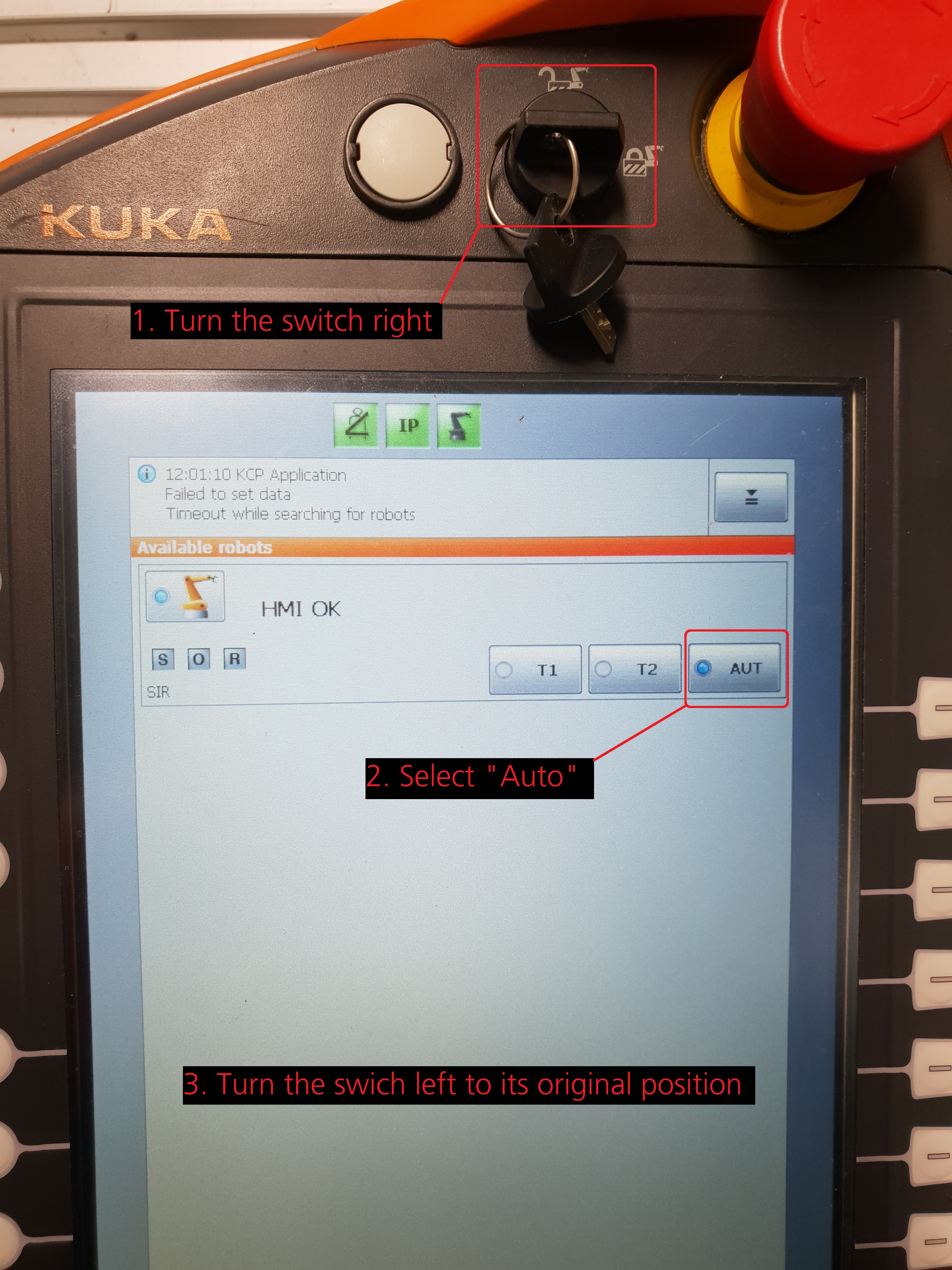
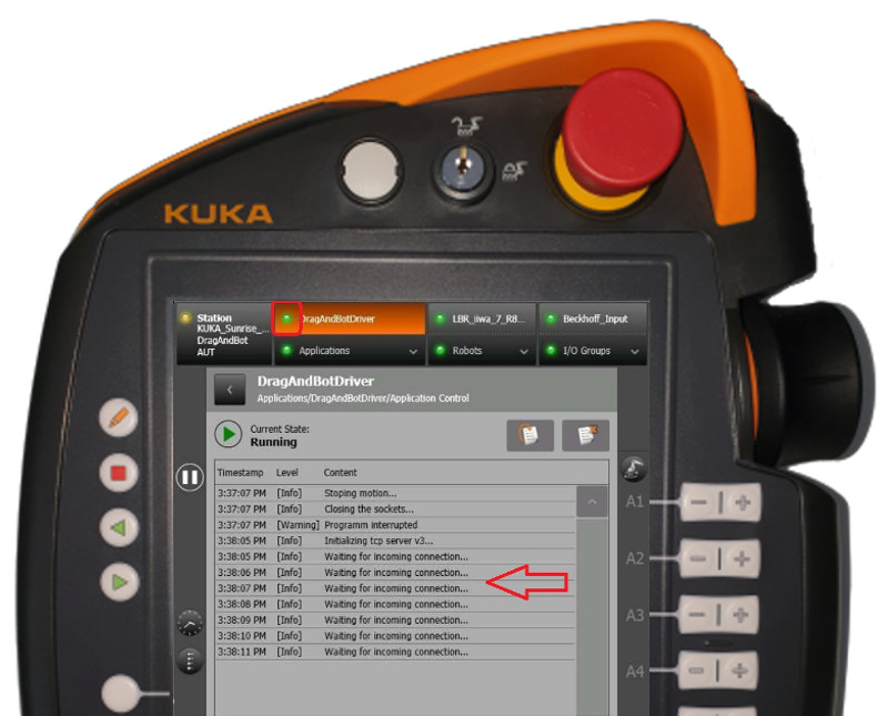
The driver needs to be started in automatic mode. Please turn the key to the right, select Auto and then turn back to the left. This method allows changing the controller between manual mode and automatic mode. The driver can also be started in manual mode, but then the safety button must be keep pressed during operation. If the application is correctly started then it will inform periodically on the screen that is waiting for incoming connection.
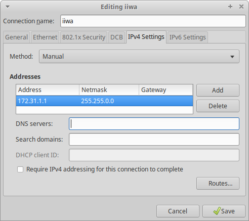
Step 2: Network connection
Connect the drag&bot IPC through ethernet cable to the robot controller. Then configure an static IP in the same range (e.g. 172.31.1.1) of the controller with a mask of 255.255.0.0. More information about network can be found in Network Setup and Robot Network Configuration documentation.
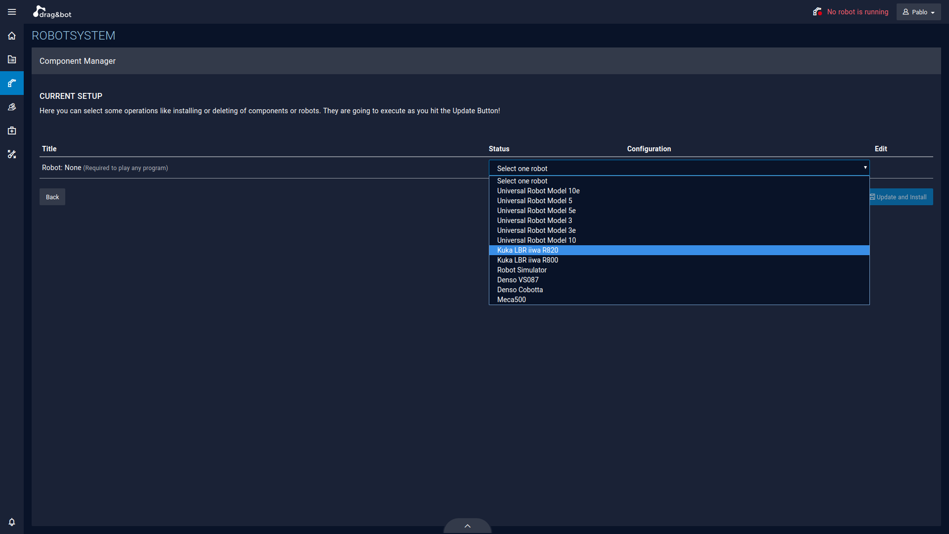
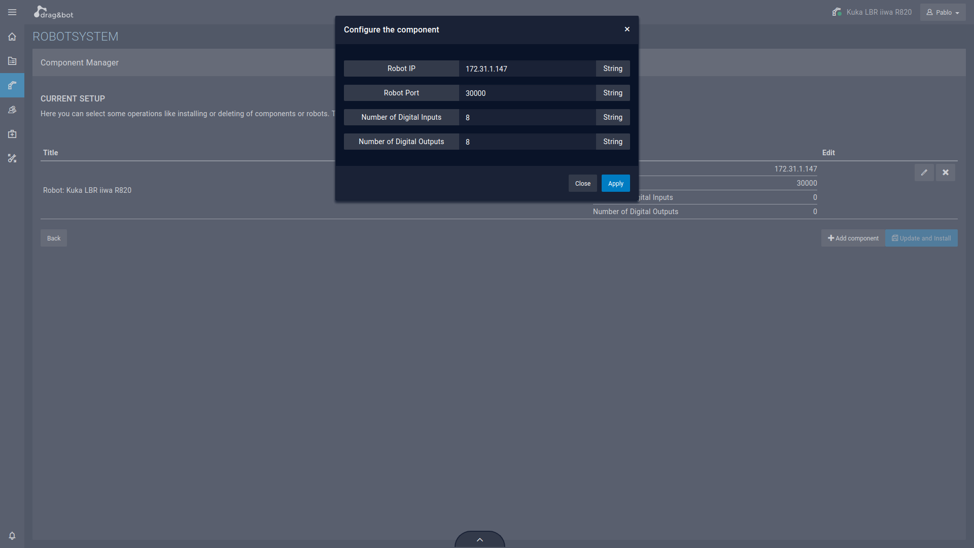
Step 3: Robot system configuration
Adding the KUKA IIWA drag&bot component is required. Detailed information about the process can be found in Getting Started section of the documentation and subsequent. You need to select the correct LBR model which may be 800 or 820. Afterwards the configuration of the target IP address and the number of digital inputs and outputs may be needed. This information is found in the IO table of the iiwa installation page.
After the driver is correctly configured, Running will be displayed in drag&bot. The teach pendant will also inform in the screen that the connection was accepted.
Function Blocks
Digital I/O - Get
Requests the value of a digital I/O pin of the robot.
| Name | Data type | Description | |
|---|---|---|---|
| Inputs | Pin Number | Integer | Number of a digital I/O pin. |
| Outputs | Value | Boolean | The value of the digital I/O pin. |
| Exceptions | ERROR_NO_DIGITAL_IO | - | The exception is raised, if the respective digital I/O does not exist. |
| TIMEOUT | - | The exception is raised, if the digital I/O state can not be requested from the robot. |
Digital I/O - Set
Sets the value of one of the I/O pins of the robot.
| Name | Data type | Description | |
|---|---|---|---|
| Inputs | Pin Number | Integer | Number of a digital I/O pin. |
| Value | Boolean | Value of the digital I/O pin. | |
| Outputs | - | ||
| Exceptions | ERROR_NO_DIGITAL_IO | - | The exception is raised, if the respective digital I/O does not exist. |
| ERROR_NO_DIGITAL_OUTPUT | - | The exception is raised, if the respective digital I/O does exist, but is no digital output. | |
| TIMEOUT | - | The exception is raised, if the digital I/O state can not be set at the robot. |
Digital I/O - Wait For
Pauses the program execution until the desired value is read on the given digital I/O pin. A timeout can be specified to throw an exception.
| Name | Data type | Description | |
|---|---|---|---|
| Inputs | Pin Number | Integer | Number of a digital I/O pin. |
| Desired Value | Boolean | The value which has to be read on the digital I/O pin to continue program execution. | |
| Timeout | Float | Timeout in seconds to wait for the signal before a TIMEOUT exception is thrown. A value of zero waits infinitely. | |
| Outputs | - | ||
| Exceptions | ERROR_NO_DIGITAL_IO | - | The exception is raised, if the respective digital I/O does not exist. |
| TIMEOUT | - | The exception is raised, if the digital I/O state can not be requested from the robot. |