Use Autodesk Fusion 360 to generate G-Code
Important
This is a simple tutorial showing how to generate a G-code program using the Autodesk Fusion 360, for more detailed tutorials please check the free training courses offered by Autodesk.
Prerequisites
- Windows PC with Autodesk Fusion 360.
- 3D model of the part with a drawn tool path in .dwg or .stl file format.
1. Open a 3D Model File
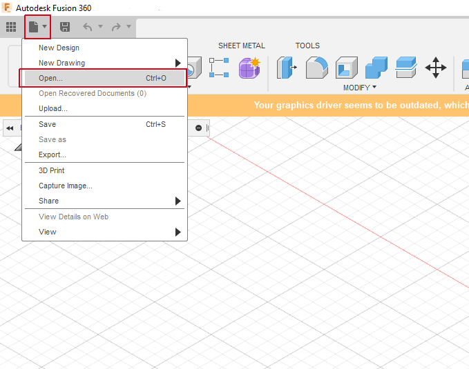
- Run the Autodesk Fusion 360, then from the file menu click .
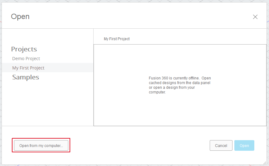
- Click on .
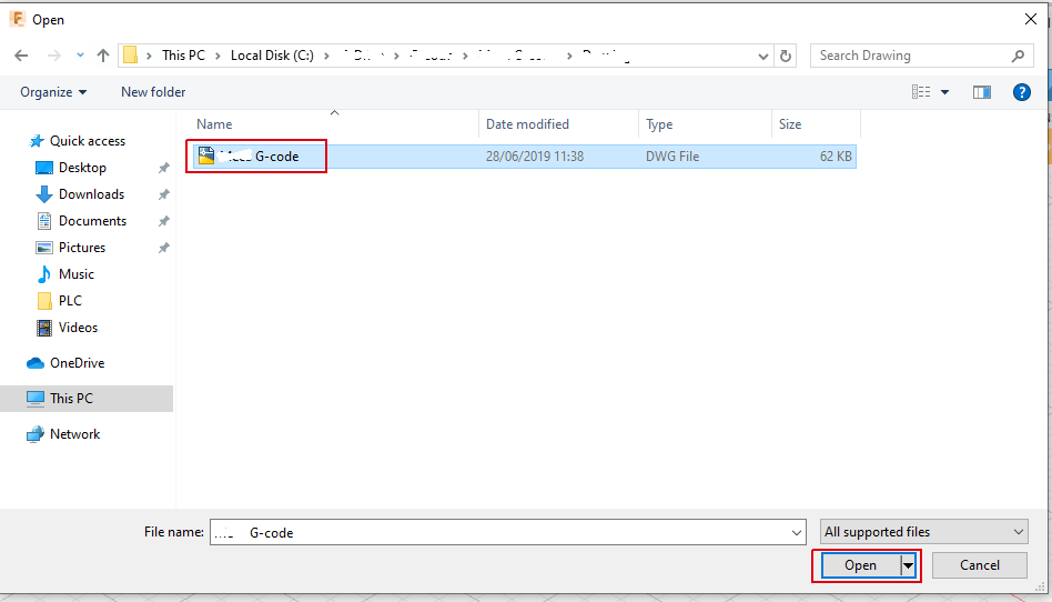
- Navigate to your 3D model file, select it and click .
- Your 3D model will be opened and shown as below.
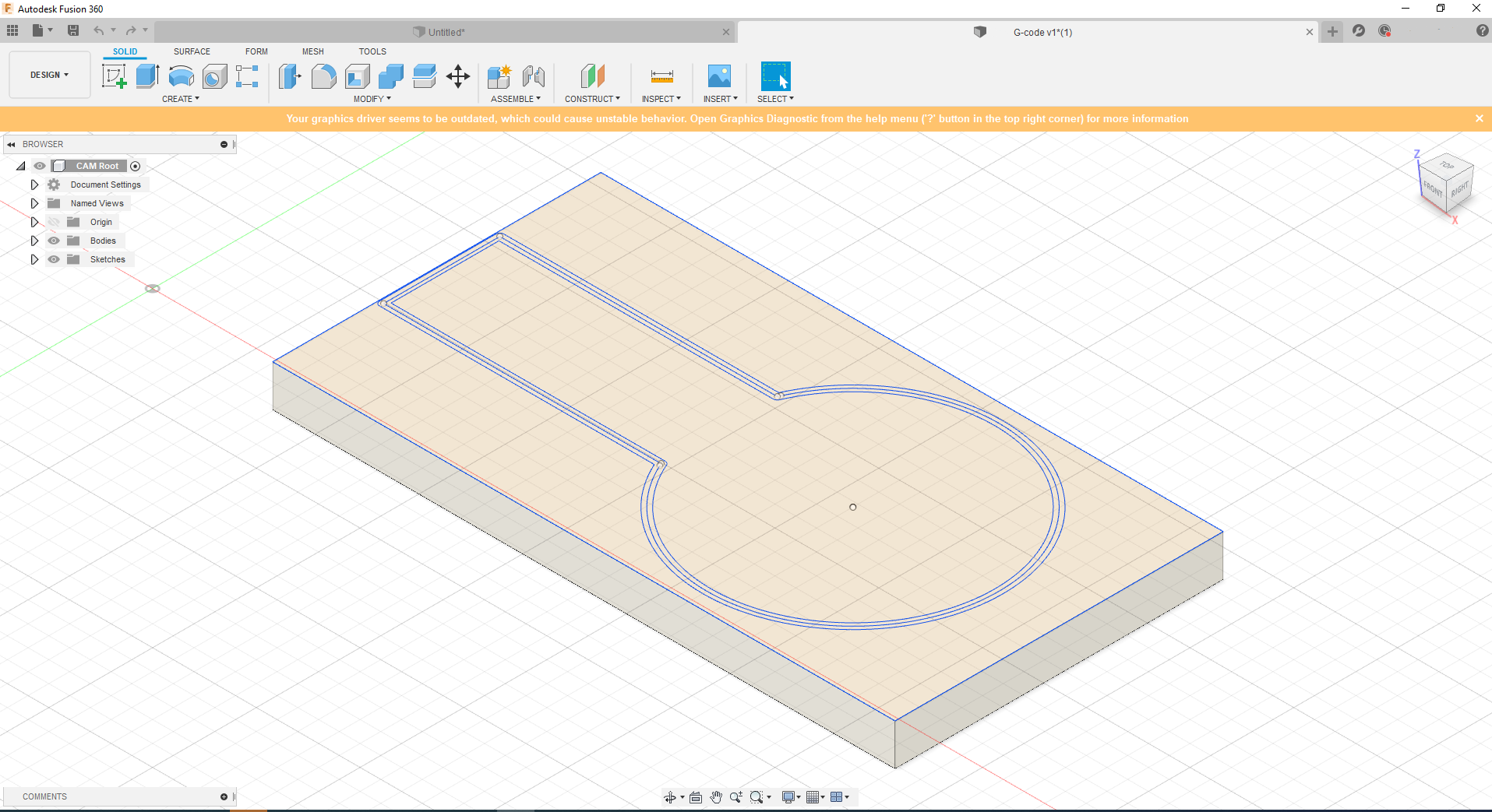
Info
Autodesk Fusion 360 may take some time to import and open the 3D model File.
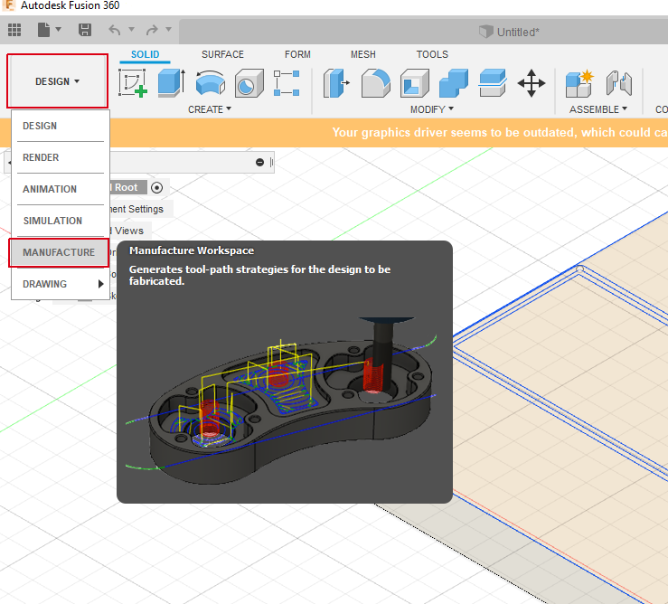
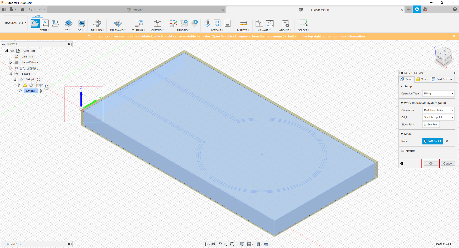
2. Configure a 3D Model
- From the DESIGN menu, click on
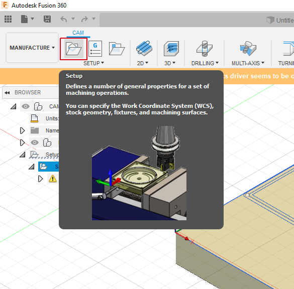
- Click on to set your model configuration (part zero, tolerance,..etc).
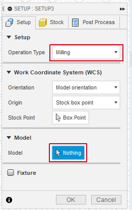
- From the Setup window, select the Operation Type, then click on the under the model section and click on your 3D model to select it.
- Click on the under the Work Coordinate System section to specify your part zero location
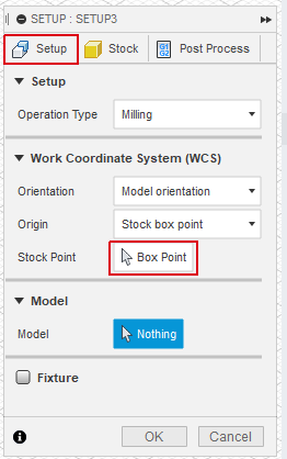
Click on the required part zero location, then click .
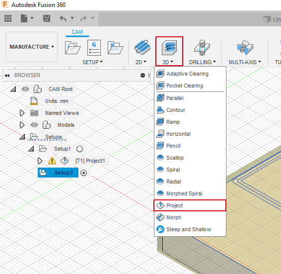
3. Create a tool path
- From the CAM bar, select the required machining task under 2D, 3D,..etc. (Note : This tuturial will use 3D->Project as an example).
- In the Project window, click on .
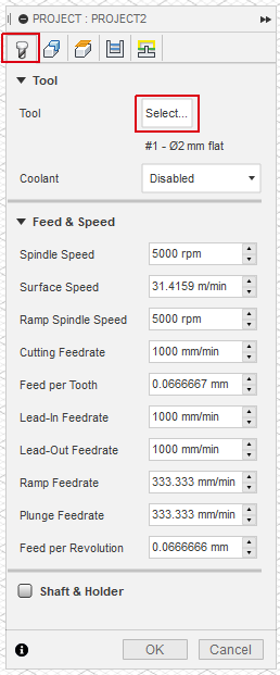
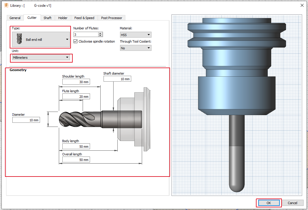
- In the Select Tool window, click on the .
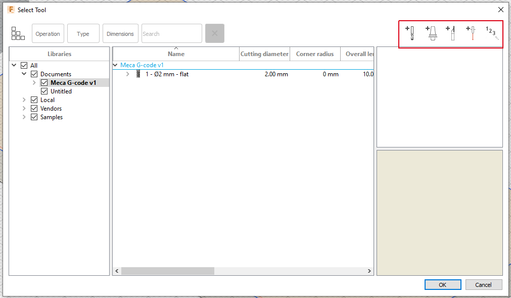
- Select the tool type, unit, and enter the tool geometry information, then click .
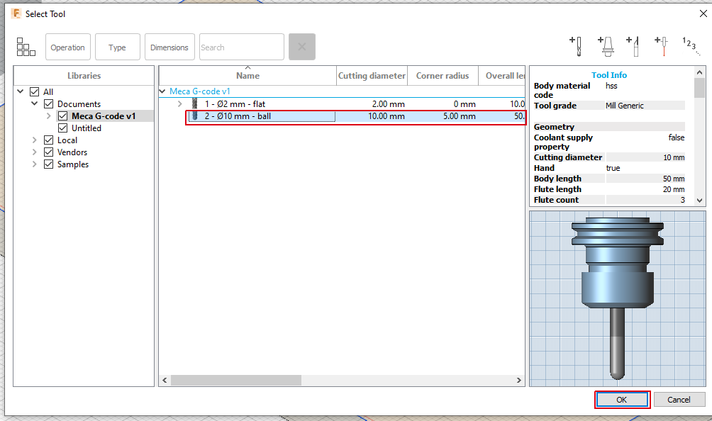
- In the Select Tool window, select the newely created tool and click .
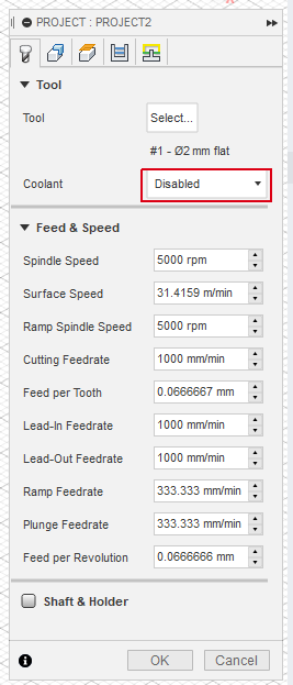
- In the Project window, select Disable under Coolant type.
- In the Project window, select Geometry tab and click on under the curve Selections, then select the desired tool path on the 3D Model surface.
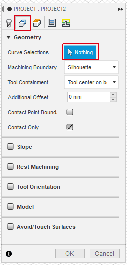
The selected tool path will be shown in Bold.
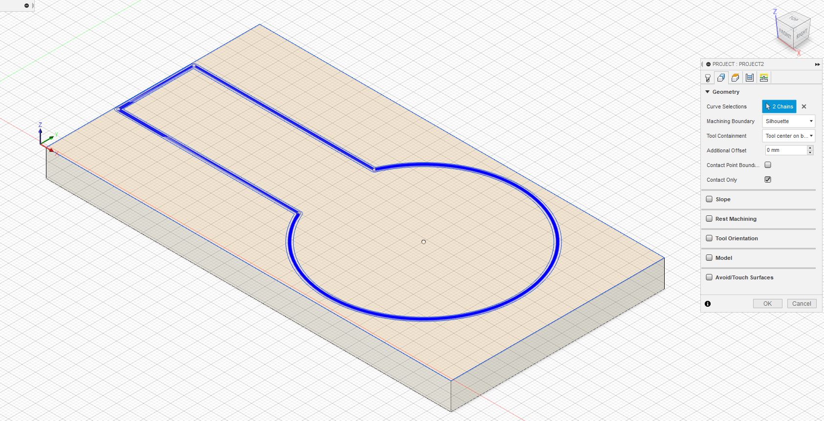
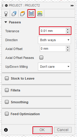
- In the Project window, select Passes tab and enter the reuired tolerance, this will effect the program size, running time, and accuracy. At the end click on .
4. Generate G-Code
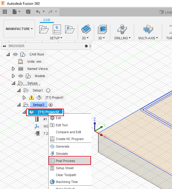
- Right click on your project setup, click on
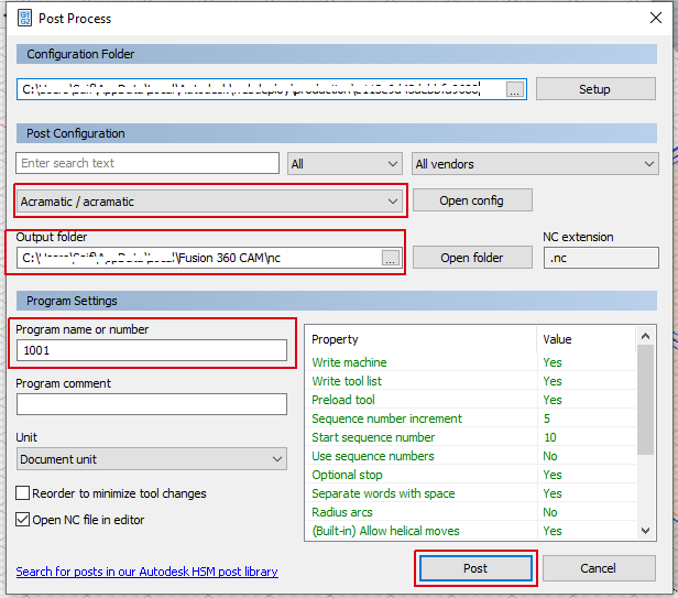
- Select Acramatic/acramatic under the post configuration, then select where to save the G-Code file and the file name, finally click on .
Info
You can change the generated G-code file extension to .gcode file manually.